JohnCh
-
Posts
3,406 -
Joined
-
Last visited
Content Type
Profiles
Forums
Store
Articles
Gallery
Events
Library
Everything posted by JohnCh
-
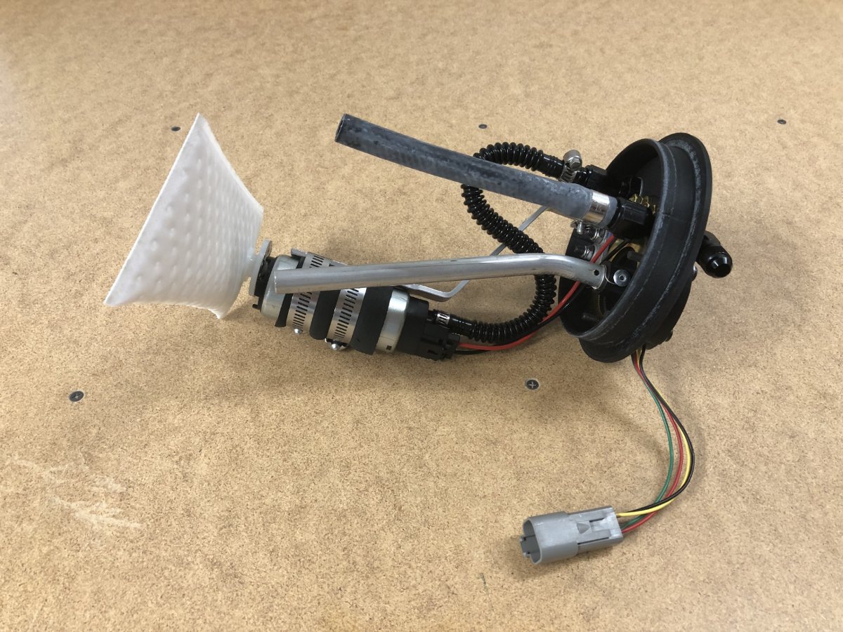
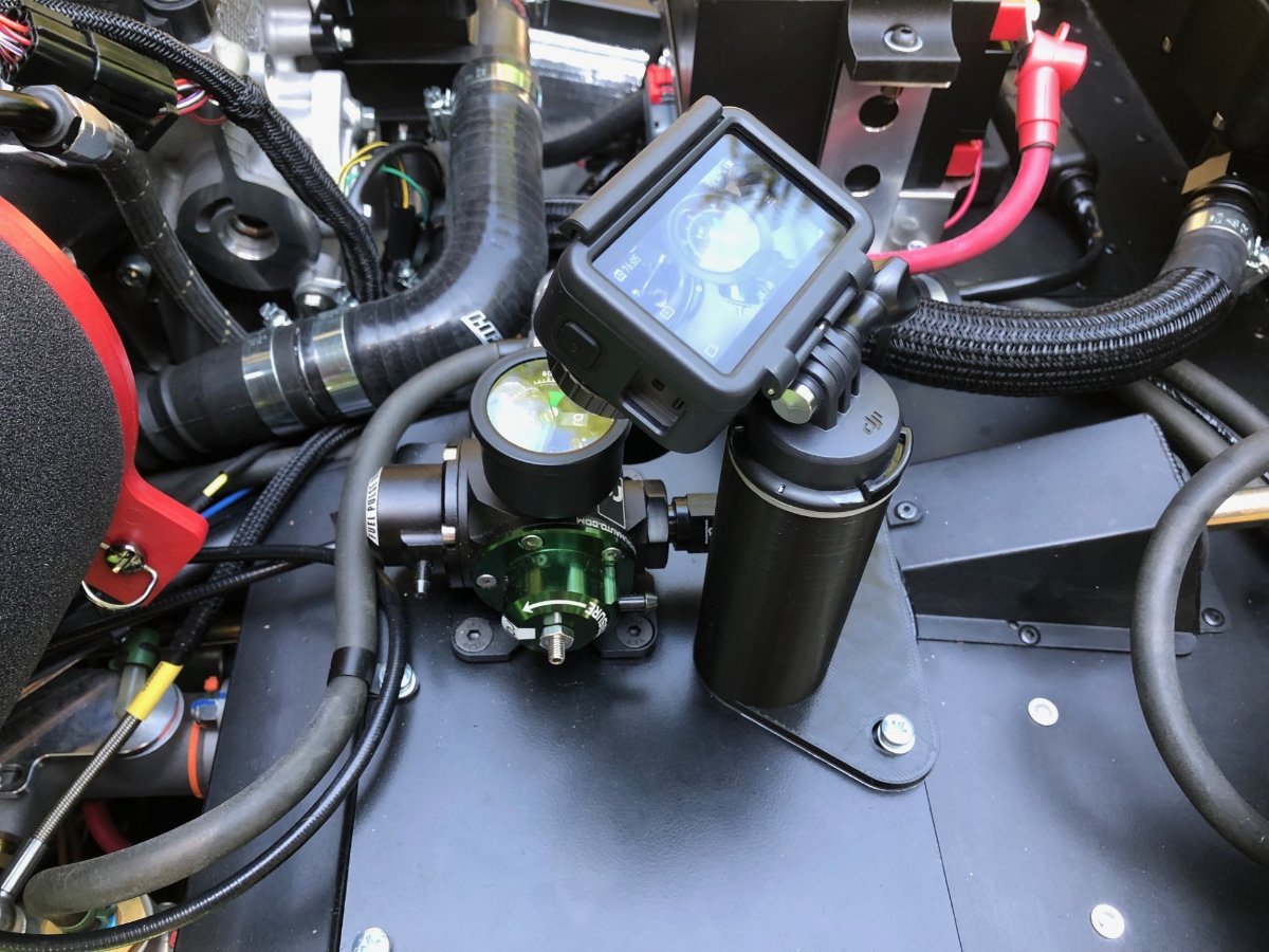
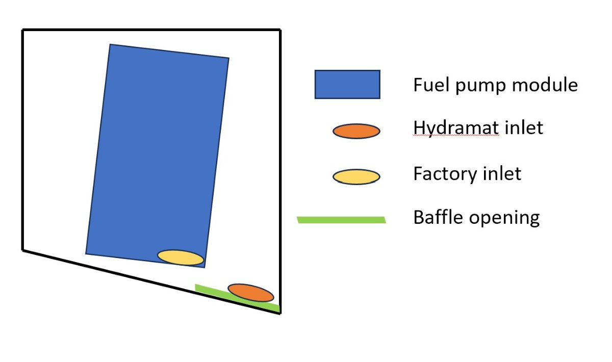
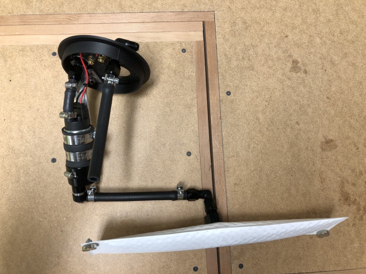
I finally received the various parts required to assemble the redesigned fuel pump module. The big change is a new, smaller Hydramat that attaches directly to the bottom of the pump, eliminating the restrictions from the earlier design and freeing up a lot of space. That in turn required a new pump bracket and convoluted PTFE tube on the pump outlet to accommodate the big S bend. Unfortunately, a quick 200' drive on my property resulted in the same behavior as seen before: full lean, stalls, easily restarts, then repeats about every 200'. Argh.... With an action camera livestreaming video of the gauge to my phone and extension cables allowing me to hold the multimeter next to it, I confirmed fuel pressure drops to zero before power is cut. No doubt. this is not an ECU issue. Thinking through the possible causes given this didn't start happening until after I had covered about 12 miles, and then suddenly started doing it repeatedly with shrinking intervals, I began suspecting fuel level. It was one thing I was certain had changed over that span. Initially though, this seemed a red herring. Based on measurements and subsequent calculations performed while fabricating the new pump bracket, I had about 0.9 gallons of fuel in the tank, and the Hydramat was fully submerged. But what else could it be? The pump and fuel pump module were all new and the fuel filter and fuel lines showed no blockages. Opting to add just 1/ 2 gallon as a test, I drove it again on the same route: 200' up the driveway, left U-turn onto the lawn, then back down the driveway before turning left to face the garage. Things were better. The fuel pressure went to zero in the same spots – as I completed the U-turn and as I prepared to stop in front of the garage – but in 3 out of 4 instances, the fuel pressure recovered before the engine could die. Hmm.... Left turns. Granted these were made at idle speed in first gear, so not exactly a g-force inducing change of direction, but it was consistent. I then drove a full circle to the left at idle speed. Zero fuel pressure.. Repeated two more times with the same result. Then 3 circles to the right. Fuel pressure stayed steady at 44 psi. After adding another gallon to the tank, the issue went away when doing circles to the left. Woo hoo! My theory on what is happening and why is best explained with a cross section drawing of the tank: Note, the above is not to scale and is an approximation based on my memory. The factory fuel pump pick up is much higher than mine and misses about 1-1.5 gallons of available fuel in the tank. My setup, however, is at the bottom and in theory provides access to all fuel in the tank. The baffle separating the left and right sides of the tank that's intended to minimize fuel sloshing has its opening on the bottom front. This is below the factory pick up but at the same level as mine. This means that when turning to the left, the baffle keeps the fuel available for the factory inlet as it approaches its empty point. However, it allows the fuel to vacate to the right side of the tank under similar circumstances for my set up. Hopefully this is the issue. I'll find out tomorrow when I add more fuel and attempt road driving. Couple of other updates. I heard back from Caterham about the wires feeding the fuel pump. They are 2mm2 which is 14 AWG equivalent. That should be sufficient for the current pump, although I may still downsize it to avoid stressing the alternator during those rare times when all the big load items are on (headlights, fan, heated seats, and pump.) Lastly, after 4 long months, the no-logo ITG filter has arrived. -John

-
As MV8 suggests, definitely do a compression check. Easy way to rule out an injector issue is to swap # 3 or #4 with #1 or #2 and see if the low temp follows the injector. Do you have coil-on-plugs or the earlier coil pack? If the latter, I've had a couple of those act up over the years so that is a possibility. If you have the CoP, check the wiring at the connector to make sure things are seated properly. Probably a good idea to look over all the wiring for the injectors and ignition to make sure there is no visible damage. -John
-
Congratulations! What are your current thoughts about options and color? That info will make a great starting point for the conflicting advice that is sure to follow -John
-
Glad to hear it's sorted! That's a lot of work to perform on a new-to-you car, but hopefully it's downhill from here. What did you decide to do for the replacement clutch and flywheel? -John
-
Thanks, is that an SR20? Has it been on the dyno?
-

Caterham A Frames - check them as part of your annual maintenance
JohnCh replied to Croc's topic in General Tech
Caterham switched from imperial to metric chassis around 2006/2007. A lot of parts are not interchangeable between the two due to small dimensional changes. -John -
I see you practiced restraint when choosing the engine -- that turbo looks bigger than my steering wheel! What are the specs? Cheers, John
-
The Regular Summary of Classified Ads of Se7ens Found For Sale
JohnCh replied to Croc's topic in Cars For Sale
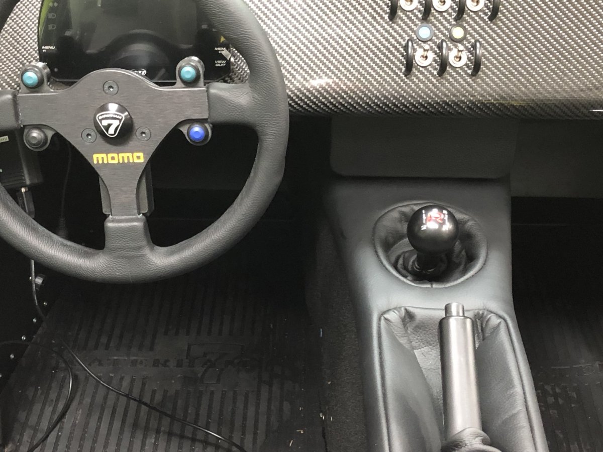
There are some interesting things on that car. It states it was a Zetec car that was swapped to a Duratec during the build. The valve cover supports that timing as the aluminum valve covers were used on the very early Duratecs people were swapping into se7ens back then. However, the seller makes no comments about how the exhaust holes were addressed and you can't see any indications on the driver's side through the wrap. Was there a reskin along the way or did Caterham supply kits back then without the cutouts? It has SBD throttle bodies, but I don't recognize the wet sump or oil filter take off. They don't look like Raceline parts. Titan may have been doing their own versions at that time. It might be a very nice car, but the steering wheel does not inspire confidence in the builder's attention to detail. Although to be fair, that looks much newer than the rest of the car so might have been added by the current owner. I wonder if there is any in-period information on this car in the California Caterham Club forum archives? -John -
This! Unless your goal is pure originality, or you plan to sell off the car fairly quickly, satisfy your aesthetic. -John
-
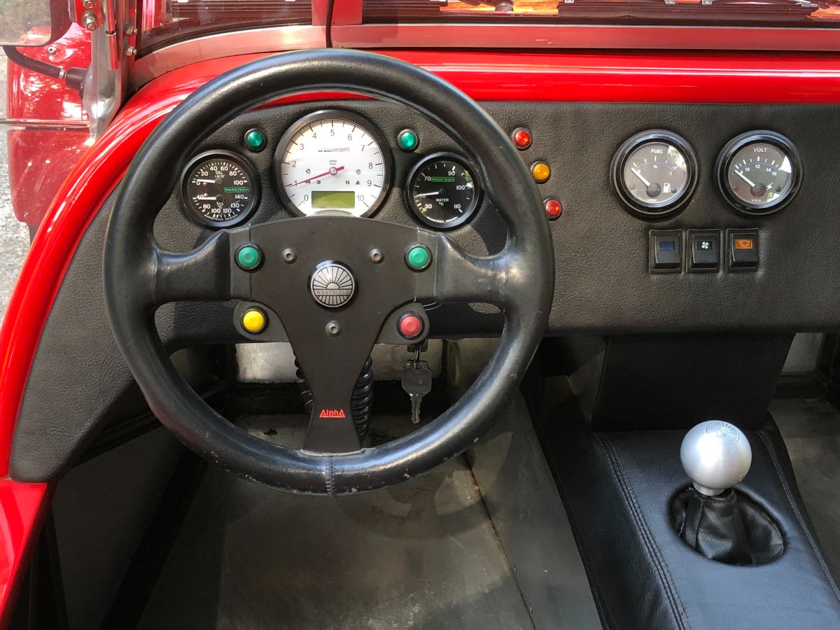
It's a last resort situation since it would require bringing the steering wheel closer to my body to gain sufficient finger clearance. I'm hoping the mount that angles the display towards the driver's face will eliminate glare issues in most situations. The Westfield has a Motogadget tach/speedo unit with an LCD display for speed and various other functions. The angle is similar to the AiM, but It doesn't have anywhere near the brightness or contrast, yet glare is rarely an issue. That gives me hope, but the only one way to find out is to drive it in various conditions. -John
-
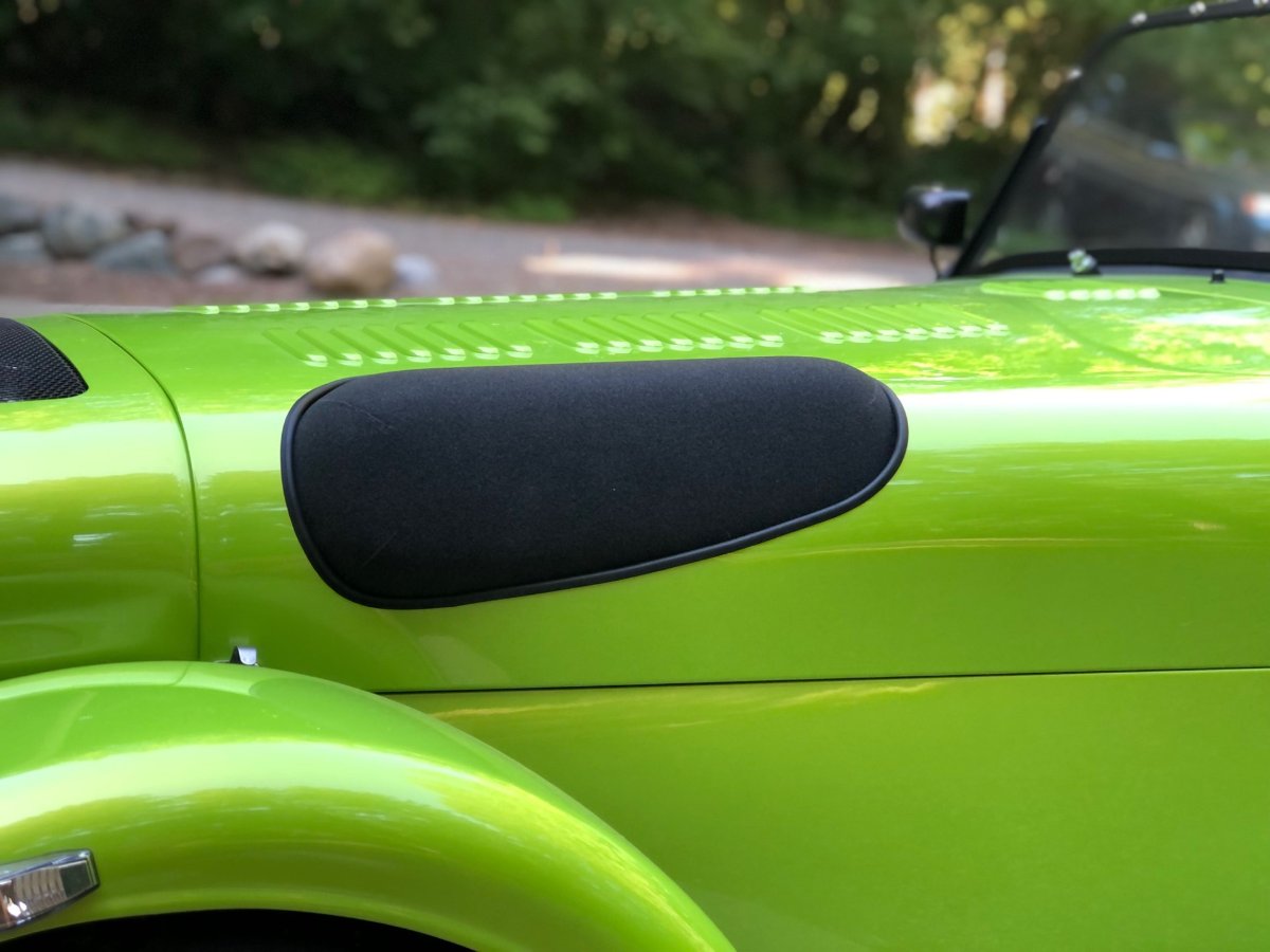
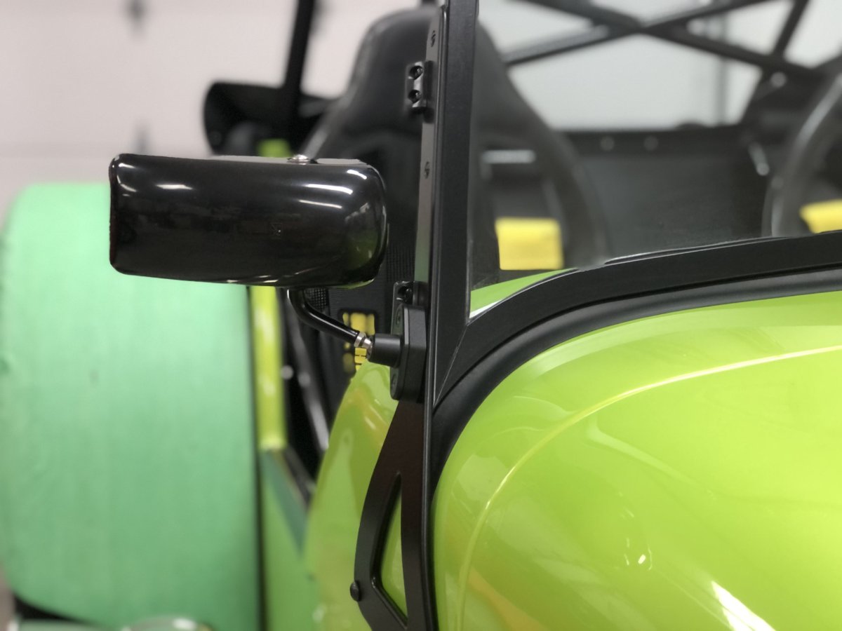
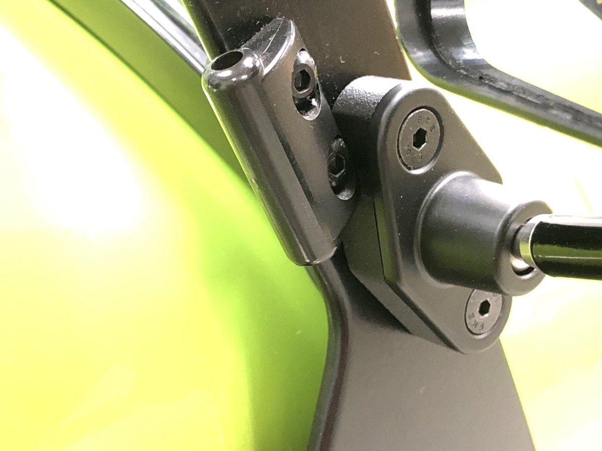
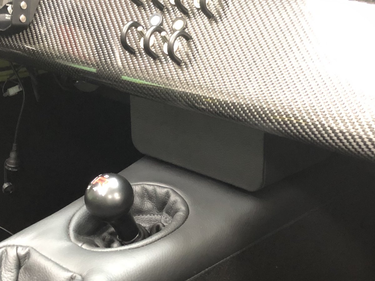
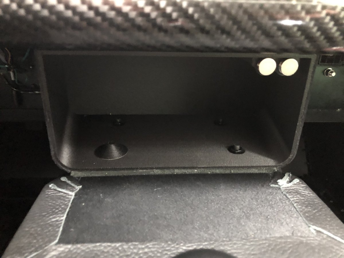
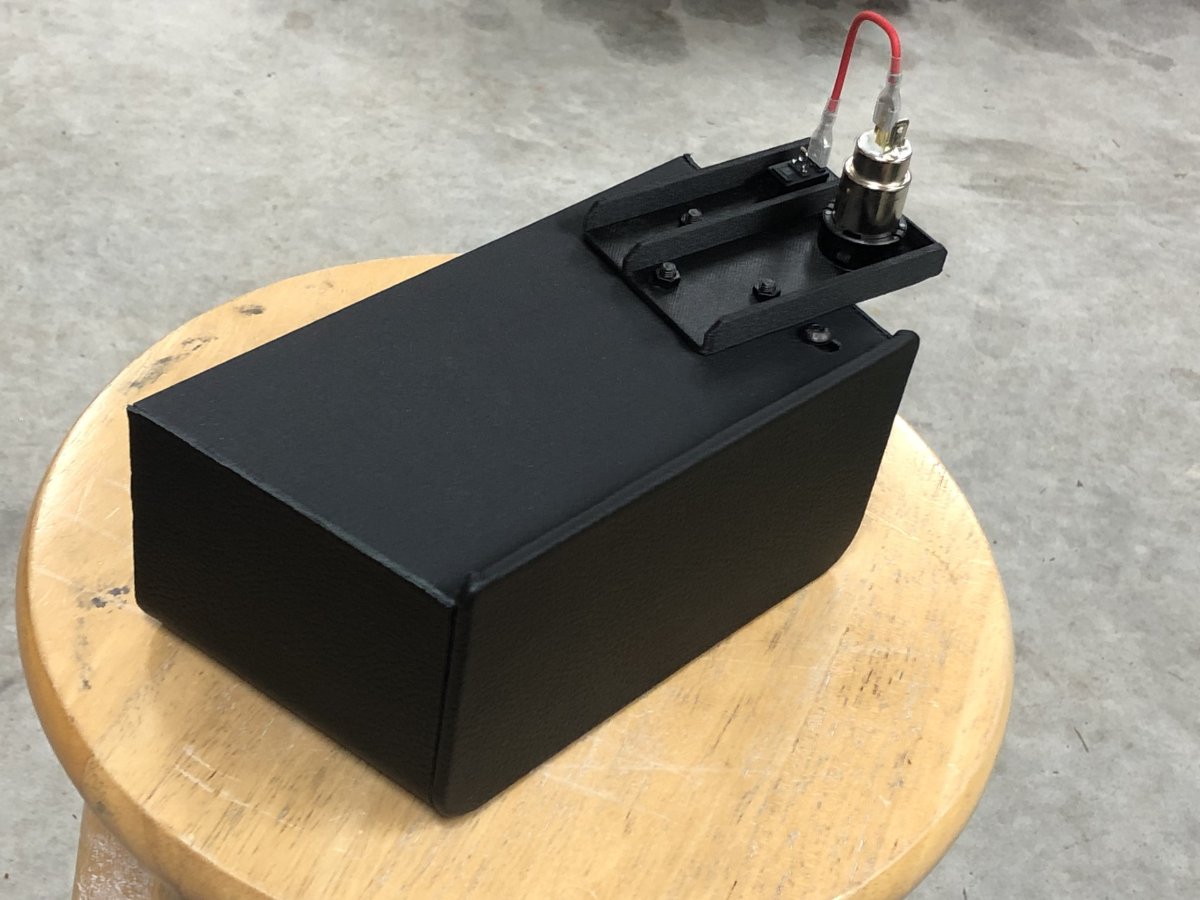
Given I'm in a holding pattern waiting on parts to arrive before I can attempt driving the car again, I decided to finish up two projects: mirror mounts and glove box. The mirrors mount fairly high on the Caterham. Coupled with the lowered floors, the mirrors are in my line of sight when going around corners; a pet peeve of mine (PM me for the full list). Using the lower threaded mounts rather than the ones in the middle, and printing spacers that work around the lower sidescreen hinges, results in mirrors about 3.75" lower than stock. Still a little higher than the Westfield, but close and it's enough to move the mirror out of the way. Next was the 3D printed glove box. Thundersport, who makes the tunnel covers for Caterham, provided a matching piece of leather with my half hood order. That covers the outside of the glove box and doubles as the hinge. Magnets glued into the lid and into an adjustable fixture that bolts to the top of the glove box keep it closed. I also added a mount for the 12v+ outlet and inserted a USB adapter which is easy to reach from the driver's seat yet not visible from the cabin. Given the parasitic drain from the USB adapters, a simple on/off switch was added to avoid battery issues. It turned out ok, but mounting was compromised. My original plan was to use countersunk screws through the bottom of the glove box, with nuts on the underside of the tunnel top. Unfortunately, the chassis has a steel plate in that location and clearance between it and the tunnel cover is really tight. The fix was switching to dome head screws that go up through the bottom of the tunnel cover with the nuts inside the glovebox. Not optimal, but good enough. A few printed caps to cover the nuts and screw ends should protect objects from scratches. V1 of the cap design is shown below. I might tweak it before printing the final set of four. -John
-
Are those the DPR mirror mounts?
-
Congratulations! Looking forward to hearing your thoughts after you've spent some time on proper roads. -John
-
Thanks @sf4018, do you happen to know the amperage draw or can you share the make and model so I can look it up? At this stage I have three options: (1) leave as-is, (2) replace the wire, or (3) replace the pump with the version rated at 165 LPH. That's still more than enough and draws half the amps (<5) but likely won't lift the fuel as strongly. I'd love to go with option 1.
-
Fair point and something to consider. I've asked Caterham to confirm the wire is 1.5 mm2 (assuming it's metric) which is a touch larger than 16 AWG. First priority now though is getting the engine running well enough that I can journey to the dyno and have the tune sorted.
-
Could the older Stalkers be a wise purchase ?
JohnCh replied to preventec47's topic in General Sevens Discussion
Given the small community of US & Canadian se7en owners, and their wide range of knowledge that spans makes, it is a conscious decision to avoid model-specific forums. If we did take that approach, we would have them for Caterham, Birkin, Superformance, WCM, Westfield, Brunton Stalker, Locost, and others. Although that may make researching a specific make easier, it reduces eyeballs on an issue as many people gravitate towards what they own, and some may intentionally avoid a specific brand forum. e.g. A Westfield owner with expertise on the crossflow, may miss a question posted to the Caterham forum about a crossflow problem because, well...it's a Caterham. Our belief is that the community is best served if we pull together and try to help each other out rather than build unintentional brand barriers. Hopefully someone -- who may or may not own a Stalker -- will answer your question. -John -
Thanks, but I'm thinking about a different direction. With the internal fittings, there is only room to raise the pump about 1/2" and still accommodate the bend in the output hose which is required for fitment -- space is really tight. Current thinking is to replace the Hydramat with a slightly larger version that positions the collector at the end rather than in the middle and attempt to position the pump end so there is a short, nearly straight shot to the Hydramat, thus eliminating both 90 deg fittings. I need the pump back to play with this and ensure I can make it work. The hoses are rated for in-tank placement. One thing Deatshwerks brought up is wiring. The pump (255 LPH) runs at a little less than 10 amps. I believe, but need to verify, the fuel pump wire is 16 gauge, which technically is fine for that amperage. Deatschwerks, however, likes to use 12 gauge wire. Running new wire is doable, but a pain. Any thoughts there? Is anyone running a larger pump with stock Caterham wiring? Thanks, John
-
I heard back from Deatschwerks. The pump passed the warranty test, but during the endurance test there was "a slight hiccup in amperage most likely from brush break in." They feel it's within spec but opted to replace it in good faith. I also purchased injectors from them and made a few pre-sales technically enquiries during that process. Every experience with them has been very, very positive. Even opening the support ticket online resulted in a response within 30 minutes. Deatschwerks is based in OK and worth keeping in mind for fuel system products: https://deatschwerks.com/ I'll test the new pump before making other changes. However, once the issue reappears or I am confident that was the source, I'll update the in-tank plumbing to minimize resistance. -John
-
When you aren't following a well-traveled path, issues are expected, and in a twisted way, part of the fun. Quite frankly, I'm really surprised this is the first real problem I've encountered, but if indeed it is a confluence of design elements in the fuel assembly, it should be a relatively straightforward fix. I've already redesigned the assembly lid to retain both the fuel pump bracket and return hose fitting while adding a massive inspection port which should take the guess work out of the equation. I'll print that later today. And if you think this is challenging, imagine how hard it must be to ensure all the correct parts are included in an expensive kit. Caterham has been doing this for 50 years, yet they still can't figure out how to do it -- it must be monumentally hard <sarcasm mode off>
-
I just had an interesting conversation with Holley. There are a few potential issues with the installation that could create either too high a load for the pump ( @Rosteri's theory) or over aeration of the fuel from the return line ( @sf4018's line of thought). Looking at the photos of the assembly out of the car, and remembering the fuel level when I removed it, made me realize that the return may have been hitting the floor and aerating the fuel. If excessive, this could cause issues for the Hydramat. More likely though is the two 90 degree fittings and 12" of hose between the Hydramat and pump creating too big a load for the pump to overcome. Another possibility is that hose rides up the slop of the tank floor, creating a high spot in the routing that traps an air bubble. While I wait for the pump to be returned, I'll print a new fuel assembly lid with inspection ports to let me see how everything sits in the tank, then figure out a game plan. It most likely involves a new Hydramat with an offset collector that can be placed closer to the pump, and possibly changing the angle of the pump mount to allow a straighter shot to the Hydramat fitting. Thanks for the insights and stay tuned. -John
-
Thanks @Anaximander, the stalling began after driving 2 miles in a neighborhood with air temps around 58F. I'm not sure if that combination is sufficient to create pump or fuel overheating issues, but I'll ask Holley for more info on this when I speak with them.
-
It's designed to work with either return or returnless and with much higher flowing pumps than I'm running. For return style, they want the hose pointed about 1" above the collection point. I believe that's how I installed it, but given it's somewhat blind, it could be off by a bit. I'll ask them about that as well. Thanks, John
-
I did confirm there was fuel in the tank when I removed the fuel pump -John
-
Oops. Fair point. I'll call Holley and ask if there are any undocumented recommendations regarding fuel pump compatibility. I suppose another remote possibility is the hose between the Hydramat and pump is collapsing. I'll examine that closely when I reinstall the pump. I still wonder about the weird TPS spikes as the engine stalled.
-
Thanks @Anaximander but I have already fabricated the module as shown below and have the Hydramat, so the only difference is the pump, which seems to be one of their standard in-tank pumps. Thanks, John