JohnCh
-
Posts
3,406 -
Joined
-
Last visited
Content Type
Profiles
Forums
Store
Articles
Gallery
Events
Library
Everything posted by JohnCh
-
@Bob.Dobos, Fejer category is added. Please send files to @Croc. Thanks, John
-
Scheduled to arrive at its new home on Tuesday
-

Best wheel and tire size for street use
JohnCh replied to Wayne Stambaugh's topic in Wheels and Tires
I broke this off into a new topic since it was appended to the thread about looking for Jake LaMont's book on building an engine. One of these things is not like the other -John -
Found the problem and the fix has been made. It now works correctly for my test account but might take up to 24 hours to fully propagate. @TEM when you get a chance, will you please change your email address back to gmail, then send me a PM so we can test it? Thanks, John
-
Those are not the issue here based on my limited testing last night with a newly created gmail account. I also confirmed the new account can receive an email directly from the gmail account used as the send-from address for notifications, so that address is not being blocked. I suspect this might be related to the extra routing from mails that go through our hoster's UK servers, but the lack of consistency is odd. Having more data points of people who are seeing this will help me do further digging on commonalities that will in turn help with any support tickets I need to open.
-
Thanks @panamericano and @thewebgal. Now we know it works in some cases, and I suspect most, which is why this hasn't arisen before, but we still don't know the frequency of the problem. Are there any others for whom it is not working?
-
You're the first to report this. I just created a gmail account and confirmed I am seeing the same behavior. Is anyone else seeing the same thing or are notifications to your gmail address arriving correctly? Thanks, John
-
The Regular Summary of Classified Ads of Se7ens Found For Sale
JohnCh replied to Croc's topic in Cars For Sale
Interesting. The only photo I received was taken in a dimly lit portion of the factory by my dealer when he was there. Other requests were ignored. They must have known I was a Westfield owner I had wondered about a Rich Kamp connection but didn't find anything on his website. It's a nice spec and the asking price is just about what it costs at current currency conversion rates less the international shipping. -
The Regular Summary of Classified Ads of Se7ens Found For Sale
JohnCh replied to Croc's topic in Cars For Sale
Good catch. Not only not CA plates, but not US plates. This one shows a building with Caterham signage and RHD cars in the parking lot. Given it's a '21 model year and not yet completed, I'm curious to hear the back story. I suppose it could be a scam, but they would certainly be chasing a very limited market. -
The Regular Summary of Classified Ads of Se7ens Found For Sale
JohnCh replied to Croc's topic in Cars For Sale
That's a nice spec. Provided someone likes the color, it's an interesting option for someone considering ordering a kit. Given it's in Sonoma, I wonder if Kampena Motorsports is involved in some way? -
@ashyers brought this place to my attention a few years ago. Huge array of O-rings: https://www.theoringstore.com/store/ -John
-
ID
-
Last night I finally got around to updating my website with the Caterham story. While uploading photos to the modifications page, I realized I didn't have one that showed the 3D printed battery hold down, fuse box lid, and coolant junction cover together. Given they share the same ribbed design with the hope of making them look more cohesive and intentional rather than haphazard choices, that was a miss and was addressed this morning. Adding that photo here as well to show the end result. -John

-
I drilled out a lowered floor rivet, then riveted one of the spare cable tie wrap mounts in its place. Lousy photo, but it should give you an idea. -John
-
Filter is sold.
-
I had the same question so asked Raceline this morning. Peter said it's 22mm x 2mm.
-
New set of Bilsteins w/Sport Springs from 420R - SOLD
JohnCh replied to JohnCh's topic in Parts For Sale / Wanted
These are spoken for. I'll update the listing to sold once the deal is done. -
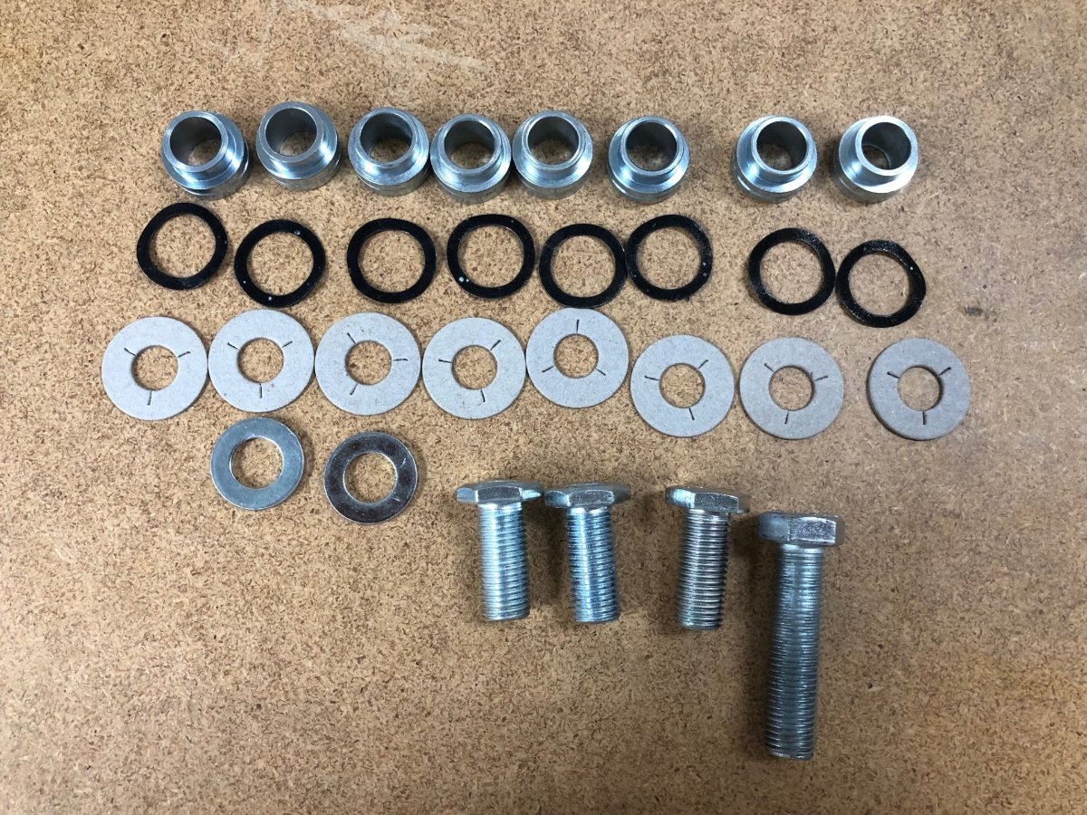
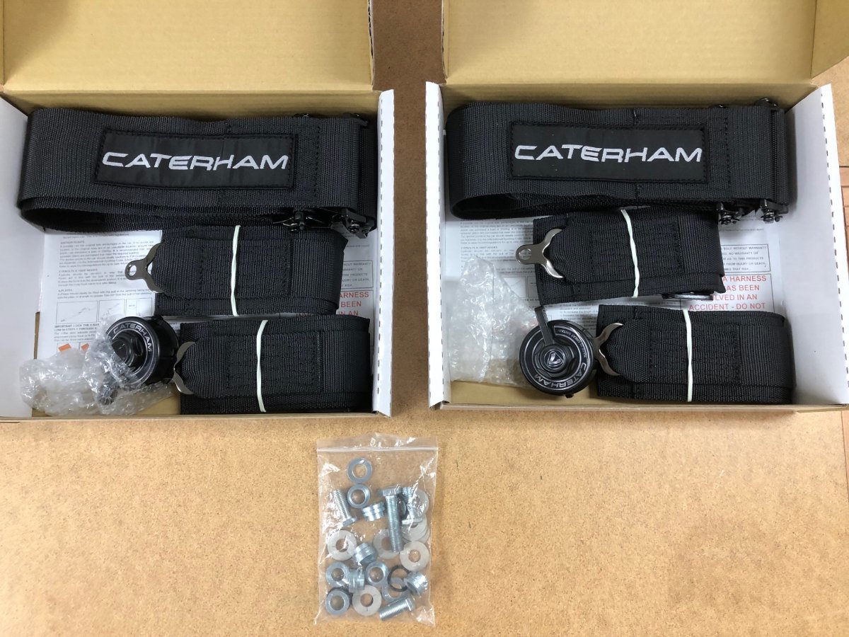
Two unused sets of Caterham four-point harnesses as supplied new with my 420R kit. Included hardware is missing a few standard washers, 3 of 4 shoulder bolts, and 1 lap belt bolt. All other fasteners, including the more difficult to acquire locally swivel inserts, wavy washers, and fiber washers are included. These belts are not supplied from the factory with date codes. Current factory price excluding VAT is 469 GBP for the pair, or $574 at today's exchange rate. Asking $450 $300 https://caterhamparts.co.uk/seatbelts-harnesses/7525-seatbelt-4-point-quick-release.html -John
-
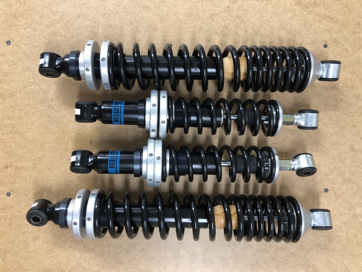
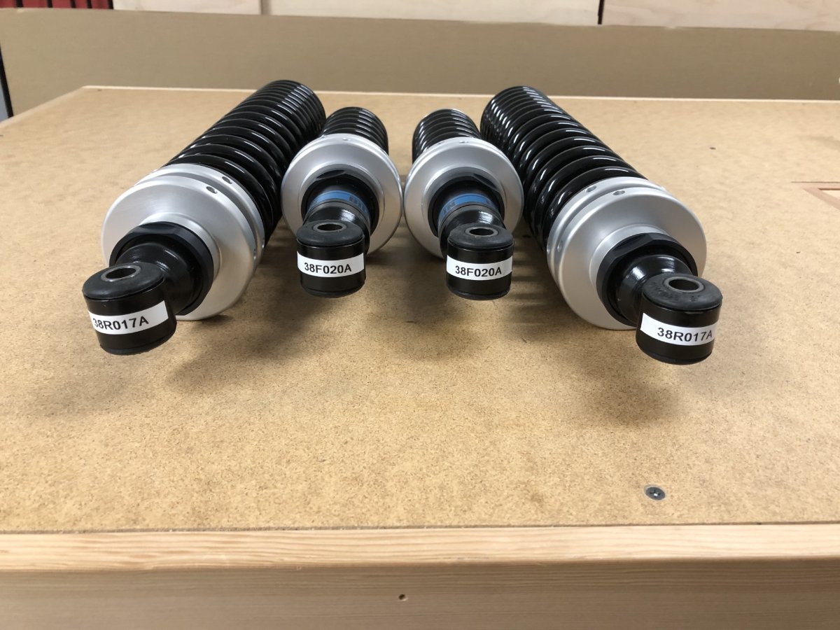
Brand new Bilstein dampers and springs take offs from my 420R kit. As per Caterham, these fit both the SV and S3 chassis provided the latter has the wide track. Spring rates are 170 lb fixed-rate front, and 140 lb progressive on the rear. Links to the parts on Caterham's parts side are below: Front: https://caterhamparts.co.uk/dampers/4614-damper-and-spring-front-420-road-specification.html Rear: https://caterhamparts.co.uk/dampers/2881-damper-and-spring-rear-420-road-specification.html Current price excluding VAT and international shipping costs is 607 GBP for the set, or $743 at today's exchange rate. Asking $500 plus shipping. -John
-
Almost new ITG JC50S/125 sausage filter for sale. After waiting 3 months for my special order version with no logo to arrive, I purchased this standard logo version to tide me over and allow me to proceed with my build. The no-logo filter arrived a few weeks later and this filter was returned to the box after covering less than 50 miles. There is some discoloration on the underside left where it made contact with the bonnet, but as per the close-up photo, the foam is undamaged. These are available new from Pegasus for $175 here. If this is for a new installation, you will also need to purchase the baseplate linked from that page. $100 plus shipping. -John
-
It's been over 4 years since installing one in the Elan, so my memory is foggy, but 123 was responsive to email when I had an issue with one of my iOS devices connecting to the software. You do need to trigger the LED as this confirms the distributor is at the expected location for the map advance to be correct. Two installation steps to check when doing this: The black ground wire that goes to the coil should not be connected when rotating the distributor to trigger the LED. That attaches afterwards. Make sure you are rotating the distributor in the right direction. You need to approach it from the opposite direction that the rotor spins. I seem to recall I had this backwards on my initial attempt and had trouble triggering the LED. -John
-
Ross's stories are always a great read. He has an account on the forum but hasn't visited here in a bit. Calling @I B Sevener to greet some fans and encourage more road trips -John
-
I believe you are referring to the Hydramat to pump interface. If so, the pump is using an 11mm inlet which is quite common. There are other pumps and Hydramats that use a 19mm opening. It's not that the pump needs to be submerged to prevent fuel leaking out of the body or air from sucking in. It's that the impeller must be below the surface of the fuel (i.e. submerged) so it is not lifting it, but rather is displacing it forward. The gerotor is a positive displacement style and can create a vacuum beneath it, thus generating lift.
-
Thanks, but if the low suction issue is simply down to the pump design, and a direct fit replacement is available, that seems like a lot of unnecessary work. The fact that the extra in-tank plumbing didn't create a restriction for low suction turbine impeller when it was below the fuel level, gives me hope that a gerotor pump won't have any issues and the Hydramat can do its thing.
-
I learned something interesting this week about my earlier fuel starvation issues. During troubleshooting a couple of months ago, multiple conversations with both Holley and the pump manufacturer resulted in a consensus that the pump to Hydramat plumbing was too restrictive. Those restrictions were subsequently removed but the issue persisted, which then pointed a finger to the tank design and the fact that when fuel is low, and when turning left, that side of the tank can quickly go dry. Fine. The Caterham stock system can't reach all the fuel in the tank anyway, so simply treating it like a smaller tank was really no different than stock from an effective capacity perspective. However, a follow-up conversation with the pump manufacturer this week contained a nugget that revealed the real reason behind the earlier issue: the turbine impellers used in most dedicated in-tank pumps, must be below the fuel line to operate effectively. The impeller occupies the bottom 1/4" of the pump body. Add in space beneath for the Hydramat plus a little buffer, this means at least 3/4" - 1" of fuel should be present in the tank for seamless operation. Now throw in the fact the Caterham tank is wide and places the fuel pump at one end, and anything less than a 1/4 tank could easily put the impeller over the fuel line on a long left turn, thus creating starvation despite the Hydramat's ability to supply fuel as long as it can touch it. The fix is a positive displacement in-tank pump that will fit the application. These can create suction and don't need to be submerged to work (or so I'm told). So far, I've only found one. The Walbro GSS341/2. It uses a gerotor rather than a turbine impeller, is rated as the same flow as my current pump and has the same 11mm inlet that works with my existing in-tank plumbing. I'll give this one a try. I suspect the lift is also sufficient that the earlier plumbing design with two elbows won't be an issue. Reverting to that version will allow the use of the longer, more centrally located Hydramat that affixes to the tank bottom, solving another issue. Unfortunately, the direct mount Hydramat currently in use can float up, contacting the bottom of the fuel sensor tube and cause wildly inaccurate readings. My plans to reorient the sensor to gain a constant 1/2" clearance may no longer be required. -John