JohnCh
-
Posts
3,444 -
Joined
-
Last visited
Content Type
Profiles
Forums
Store
Articles
Gallery
Events
Library
Everything posted by JohnCh
-
I didn't add a fuel pressure sensor (hindsight...). However, when testing in the driveway I pulled the bonnet and could see the fuel pressure regulator gauge from the driver's seat when leaning forward. It fell off a cliff when the lean spikes hit that led to a stall. To be fair, there was a slight lag as I looked to the gauge, so I won't claim 100% certainty, but it's close. The pump is out of the tank and the fuel is evaporating. I'll pack it up tomorrow and send it back for evaluation. -John
-
Here is what SBD told me: "Because you are going to be using a normal fuel pump and regulator, I have programmed the same pin to be simple on/off output to control a relay that you will have to fit which will replace the standard Ford electronic fuel pump control module. Please note that this will be a switched ground as all output are on the 9A4 ECU. " I used this waterproof relay and located it in the same location as the control module next to the tank. I have the wiring information with color codes in my notes. Happy to dig those out if you need them. As for SBD being pricey. Don't get me started. Unlocked ECU was 583 GBP, the special sauce cable to connect it to a laptop is 160 GBP, and the map was an additional 320 GBP. Any support is extra. I don't recall the exact price but it was in the 125 GBP per hour ball park. By comparison, the Emerald is 695 GBP for an ECU with a lot more features (4 wheel traction control, switchable maps on the fly, knock control, etc.), the laptop connection cable is 20GBP, and they give you starter maps gratis. They also don't charge for support and when I have offered in advance to pay for some extra help if needed, I was always told not to worry about it. Unfortunately, getting SBD to do a live session on roads is difficult for me. As @Croccan attest, cell service is really poor in my area. I may still use SBD to help with the dyno session. -John
-
Thanks, but I'm not using that controller. Since I have a return system controlled by a pressure regulator, SBD had me replace it with a normal relay that the MBE still controls for on/off only. The thinking is that if you are in a crash that kills the engine, the MBE will cut power to the pump and stop it from emptying the tank. The fact that the terminals on top of the tank, which feed the pump, were still showing 12v when the engine was going full lean and stalling, and not going to 0v until after the engine stops, makes me think it's the pump or an in-tank connection.
-
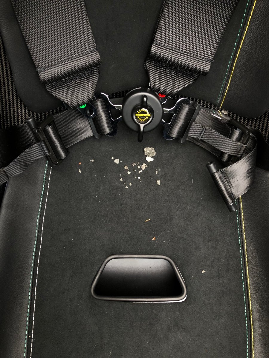
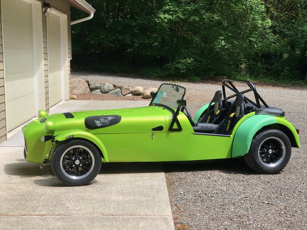
I was finally able to make time on Friday to pick up a 3-day trip permit. To make monitoring things easier while driving, the AiM display was reconfigured to show both Lambda and the TPS load site outputted from the MBE. Budget PPF was then temporarily applied to the rear wings to prevent my long gravel driveway from chewing them up, and as indicated by the second photo of the passenger seat, that was a good idea. The Avons like to throw up gravel. The first proper drive of about 2 miles revealed the map is much farther out than the 3 starter maps I've received over the years from Emerald. With light throttle, shift points around 3000 rpm, and speeds limited to 25-30 mph, the mixture was swinging between too rich and too lean. Digging into the logs and more drives totaling another 10 miles revealed both a map issue and a hardware problem. Whenever the accelerator was depressed even a very small amount, the mixture suddenly went lean, then quickly recovered. I'm assuming this is an acceleration enrichment setting that requires tweaking. One for SBD. The other issue took some troubleshooting. Initially there were very random and unexplained full lean spikes (1.22 lambda) lasting a fraction of a second and visible in the logs. On Sunday morning, after covering just 2 miles in cool temperatures, a spike was long enough that the engine stalled. Fortunately, it easily restarted. This stall-then-restart procedure happened about 7 or 8 more times on the 2 mile trip home, then several more times during subsequent driveway testing, including when the car was stationary. The cause? The fuel pump was cutting out. As a safety measure, the MBE cuts power to the pump when the engine stops. That was my initial guess as to the problem. However, multi meter testing showed 12v to the pump with the engine running, then remaining at 12v when the engine would go full lean and start to die, then 0v after it stalled and the MBE cut power. I hope to pull the pump tonight then return it to Deatschwerks tomorrow for further testing. Other weirdness, albeit minor, concerns the CAN output from the MBE to AiM. Although all the readings in AiM have faithfully followed what was showing in Easimap, load site was different. The extremes weren't too far out, with the readings in Easimap ranging from 0-14.8 vs. 1.1-14.3 on the AiM. But in the middle, things were way off. A reading of 5 in Easimap was just 2 on the AiM and a reading of 10 was just 5. As a test, TPS voltage was swapped for load site, and to my surprise the readings were once again perfectly in sync. Given the load site is a calculation based on the TPS voltage this is a little odd. Hopefully it's an easy fix with a setting. -John

-
Looks like the Admin dropped the ball here. @panamericano was trying to quote @Vovchandr who had quoted you in his response, then Panamericano accidently inserted his own text within that quote box. I try to catch these when they occur and edit them, but I missed this one. As a reminder to everyone, this User Guide addresses how to perform single and multiple quotes in a post and includes this specific scenario. There will be a test later -John
-
Good Road & Track article from last year on this subject: https://www.roadandtrack.com/car-culture/a40849184/inside-a-tuning-shop-when-the-epa-comes-knocking/ -John
-
Sadly, that list appears to include the people in the factory who assemble the cars
-
One thing to consider is the visibility/effectiveness of the indicator at night when the headlights are on. I know modern cars with DRLs doing double duty as indicators dim the output of the DRL on that side, but not sure how that would work when the indicator is in the headlight. Dimming the headlight seems like a bad idea, but not sure you could actually see the indicator flashing when the headlight is at full power. Has anyone been there/done that who can comment? Thanks, John
-
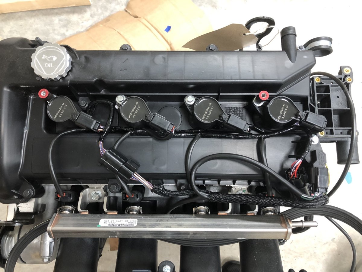
I was wrong about the location. I was going from memory and confused that connector location with the one used for the injectors. The CoP connector is shown below between the front two cylinders. -John
-
The factory immobilizer disables two functions: cranking and either fuel or spark -- I seem to recall it's the latter -- but not all three. The 420 uses a 36 pin harness for the MBE that attaches to the chassis loom, then a separate connector with a lot of pins that mates the engine loom to the chassis loom. Connections between the engine loom and MBE are hidden within the bowels of the chassis. Also, to avoid confusion, the 420 uses coil on plug not a coil pack, however, the engine loom does put all 4 CoP connections through a single connector located towards the back of the head.
-
The ECU is an MBE 9A4. 36 pins. Pinout information is here: https://sbdmotorsport.co.uk/wp-content/uploads/pdf/MBE9A4-PinoutIssue_F.pdf -John
-

Greetings and a Few Questions From a Wannabe Seven Driver
JohnCh replied to rider's topic in General Sevens Discussion
You deserve an award for your perseverance. -
Greetings and a Few Questions From a Wannabe Seven Driver
JohnCh replied to rider's topic in General Sevens Discussion
I think the key question is are you interested in learning? These cars are pretty simple to work on. Yes, some aspects are challenging, but as long as you have space, are willing to invest in tools, ask questions, and when necessary are comfortable swearing up a storm to coerce the car into compliance, you'll find most things are doable. And ignore Vlad's car. Some believe it's cursed (hmm... CURSED7 fits on a license plate, but that's a different thread.) Rumor has it a klutzy software guy was the previous owner If you are building from new, you will miss out on the joys of correcting a previous owner's mistakes and shortcuts. -John -
Tony Ingram is located in Santa Barbara. It might be worth reaching out to see if he has an opinion. http://www.lotus7.com/ -John
-
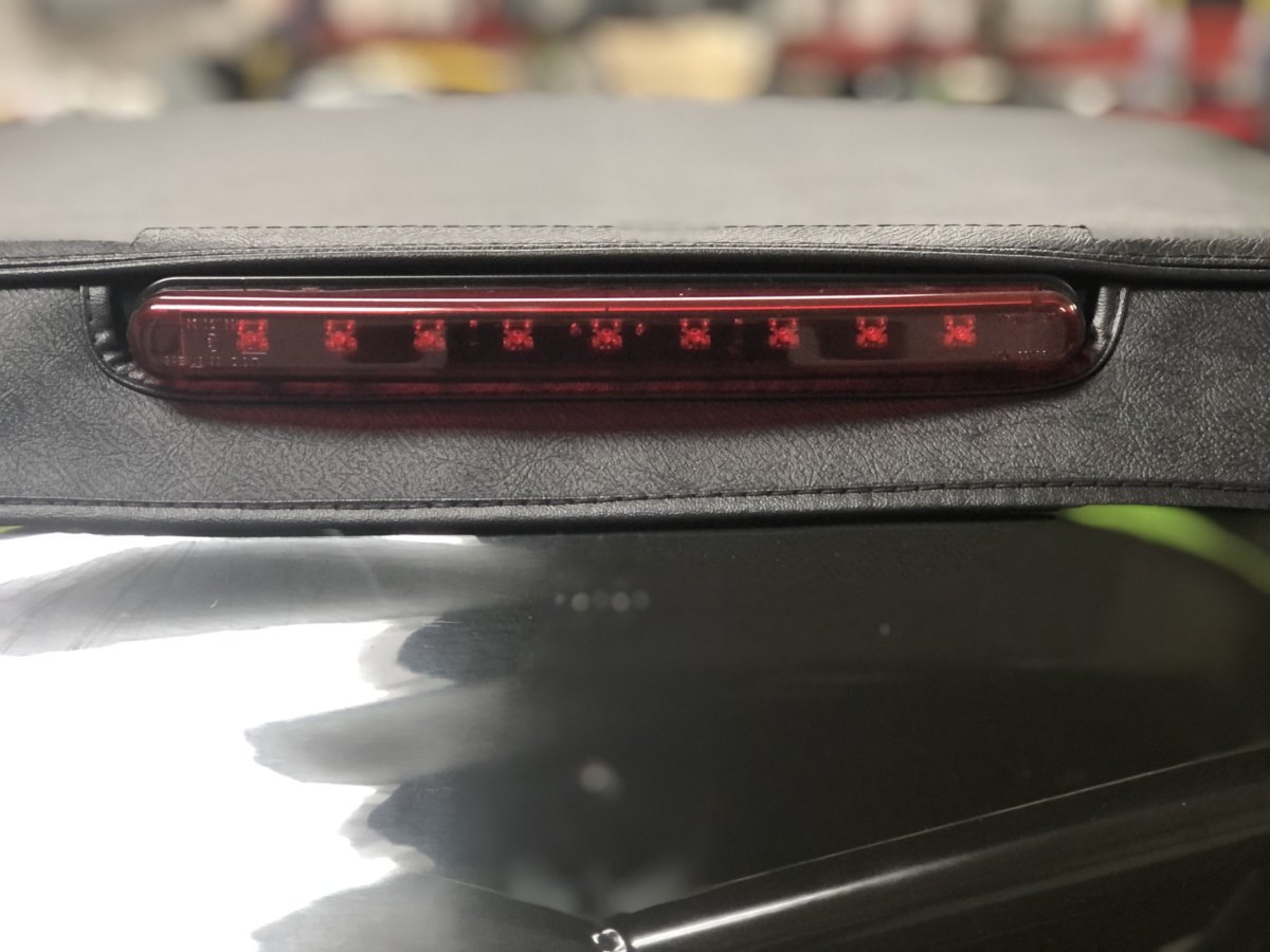
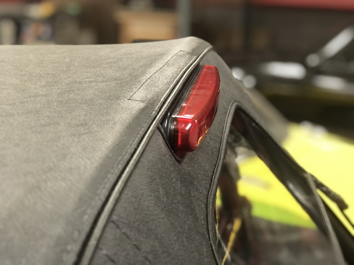
That underlayment is double the thickness of the chipboard, but clearly far more pliable given it's on a roll. The next victim should give it a try The half hood from Thundersport arrived today. The cutout for the 3rd-brake light turned out perfectly. I sent them a measured drawing and also photos with a seamstress tape measure showing the precise location from the windscreen frame. As you can see from the photos, they nailed it. I didn't expect it to come out so nicely given they weren't able to set hands on the car as per their original request; a proposal that was quickly dismissed once they understood the length of said drive -John
-
I've noticed a lot Caterhams have a very big gap, but I prefer keeping it tight, if for no other reason than the big gaps are another avenue for water to enter the engine bay. Despite the very tight gap on the Westfield, engine movement has been a non-issue over the years. I had trouble finding larger pieces of chipboard locally, so I opted for these smaller sheets from Amazon and taped them together. Worked fine. https://www.amazon.com/dp/B07BYWG8N5 -John
-
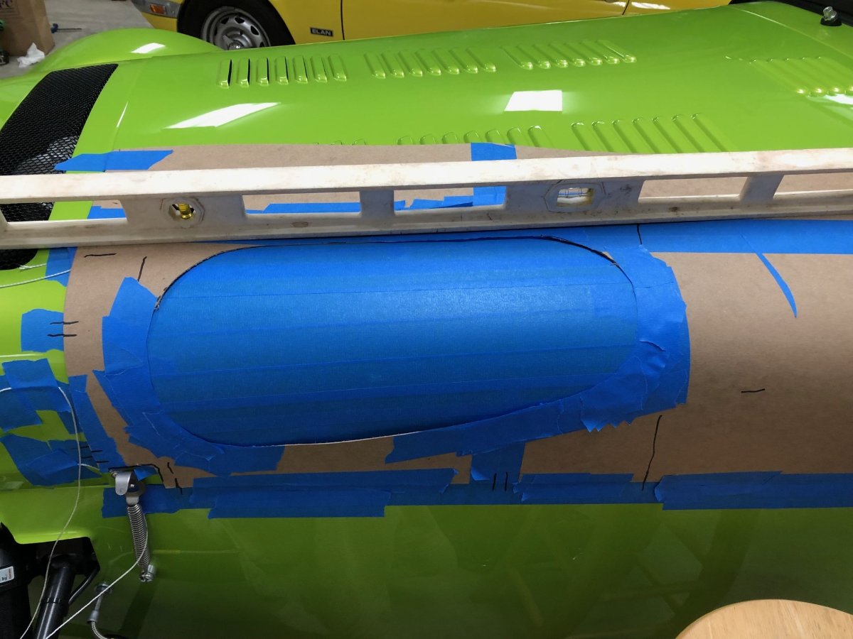
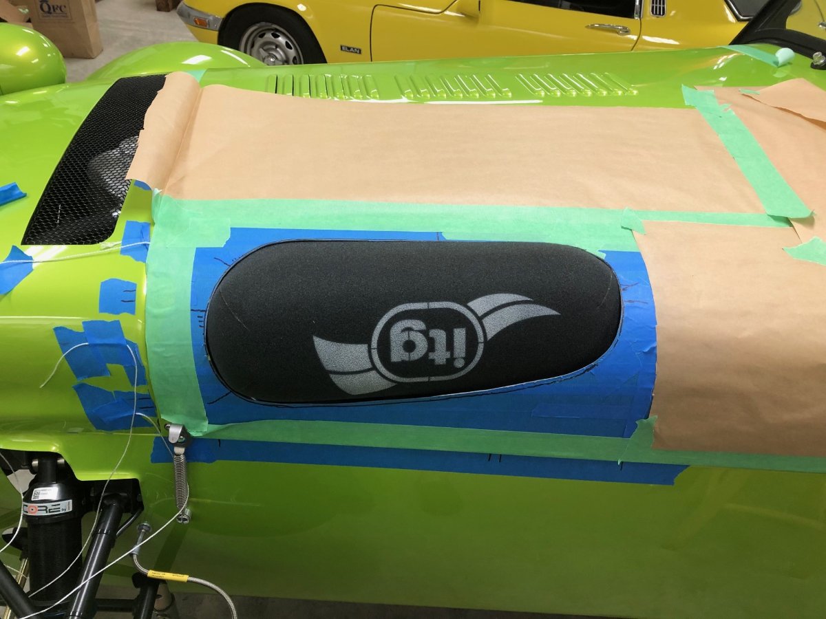
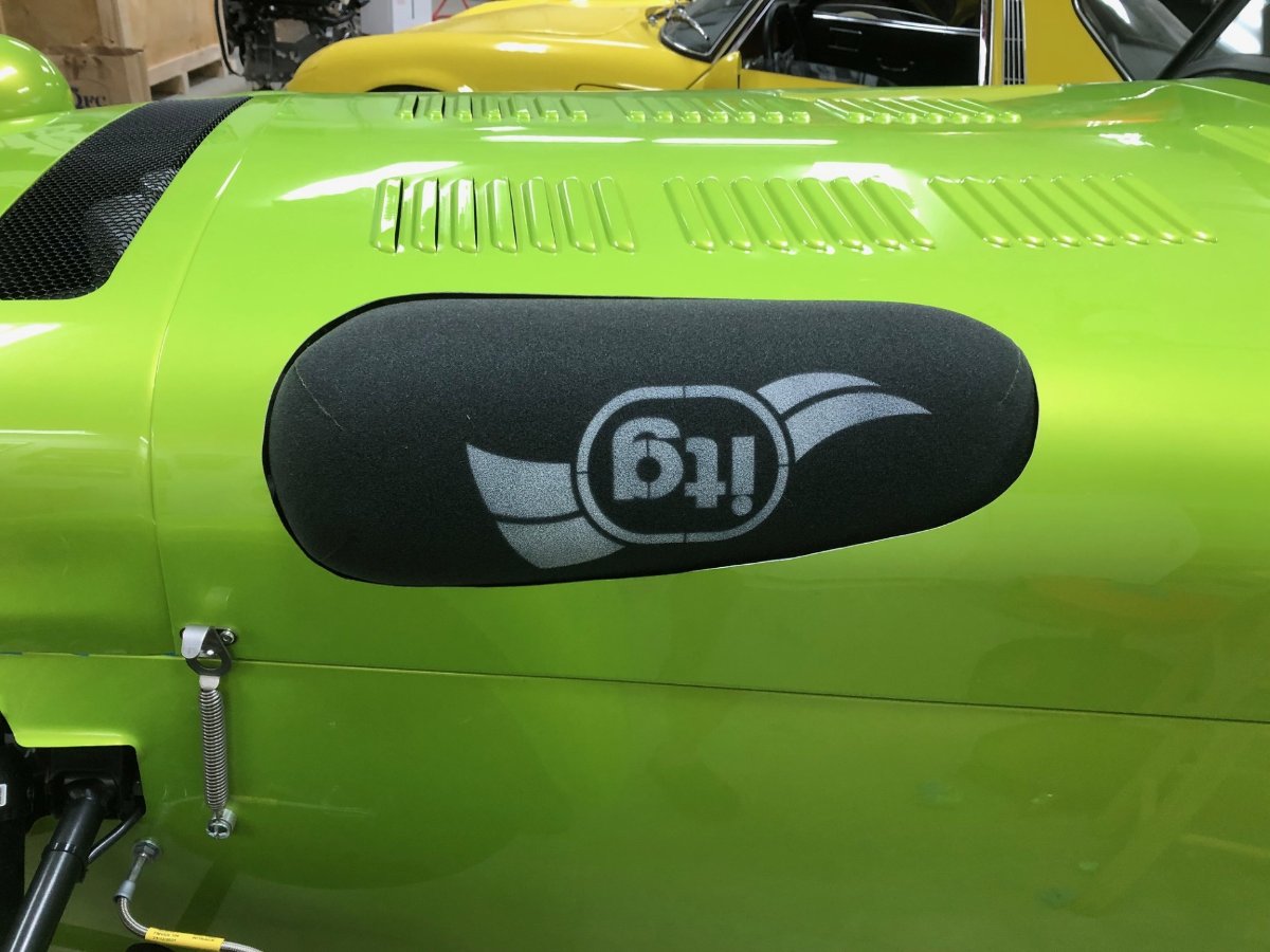
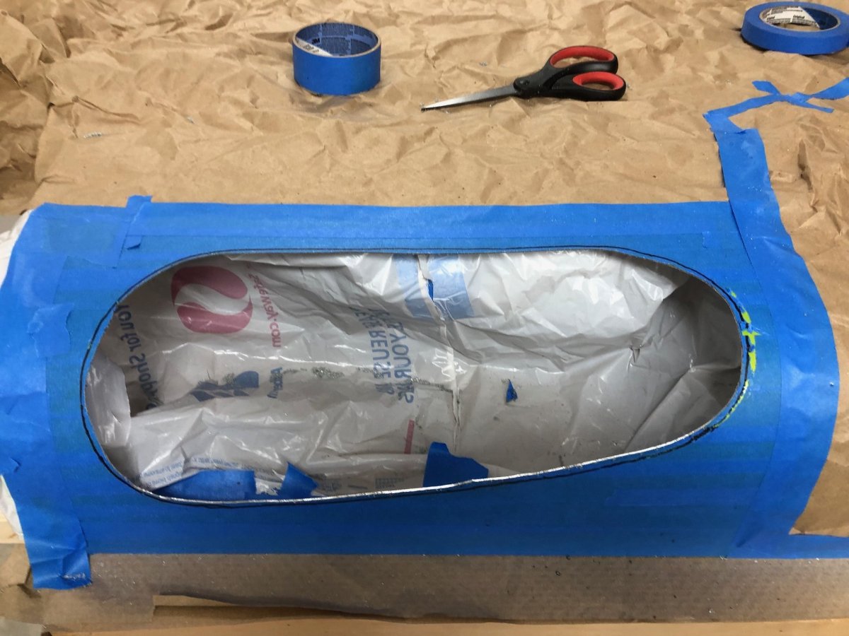
@Ferrino walked me through the process of using chipboard and recommended the air saw. Both worked great. If you are going with the big filter, I suspect an S3 will be a little easier since the filter pokes all the way through the bonnet necessitating a more uniformly oval cutout. With the SV, the rear section is partially shrouded which creates a more complex shape that can quickly go from just a little tight to way too big given how the angles work against each other. My best advice it to make the first cut intentionally too small, then put the bonnet in place to see if the location is off. In my case, the front was perfectly located despite the undersized cut. If I had cut the opening to the correct size in the first pass, the front gap would have been bigger than intended. -John
-
Definitely not. Flying a flag upside down is a sign of distress. Mounting an air filter upside down is a sign of frustration; a word that describes a large part of my Caterham experience to date -John
-
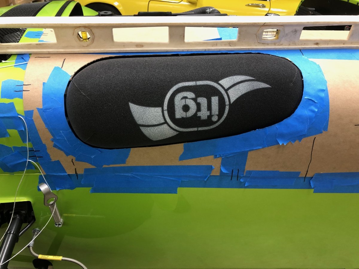
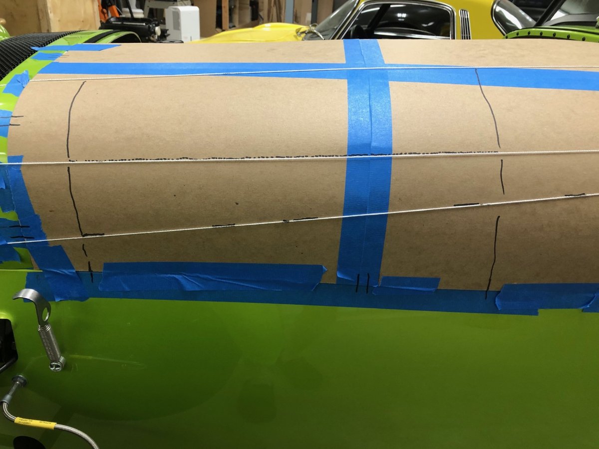
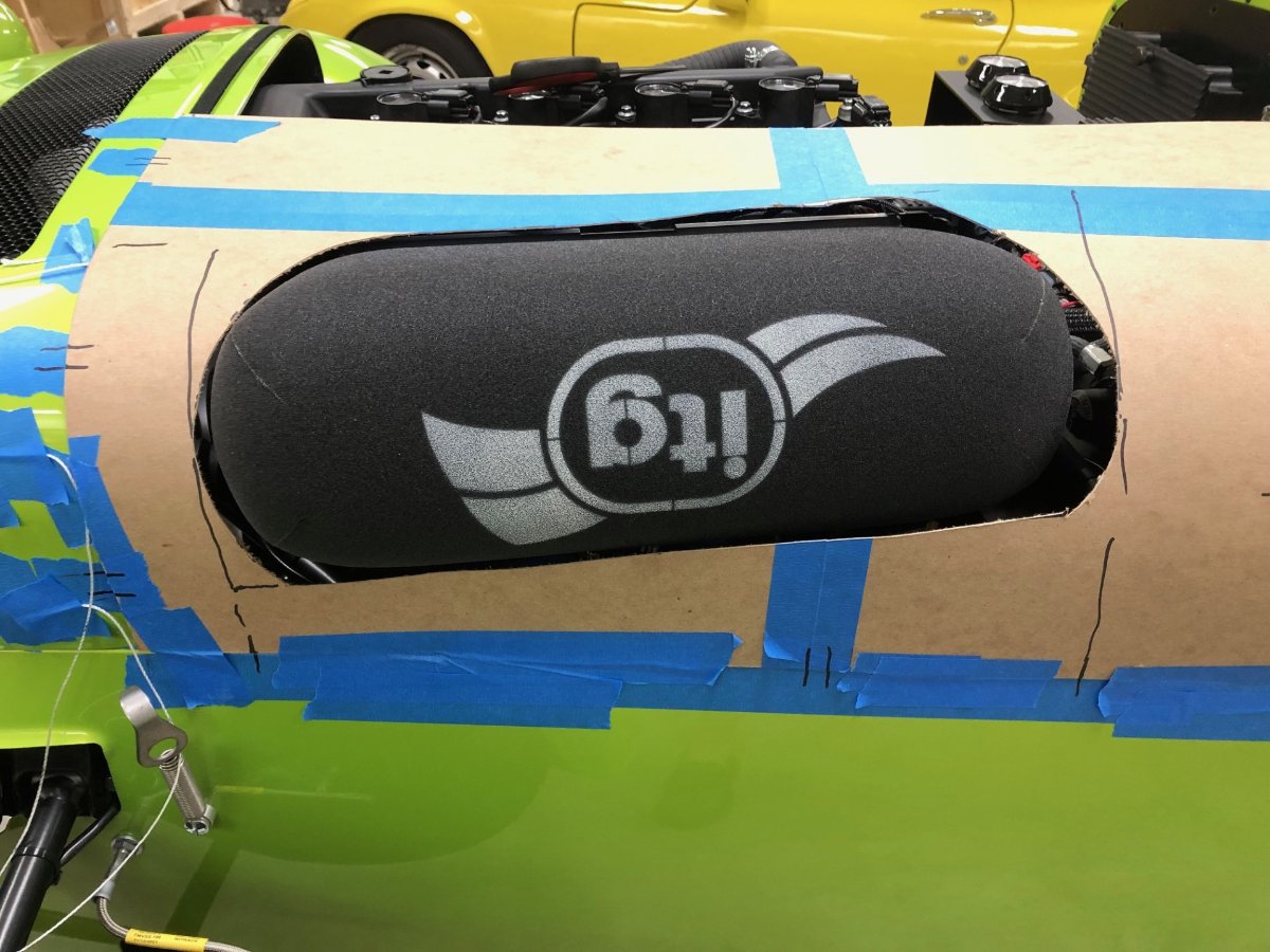
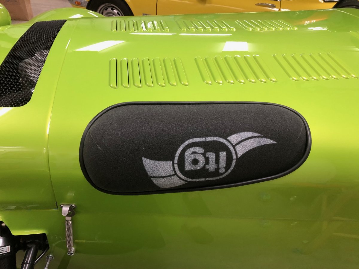
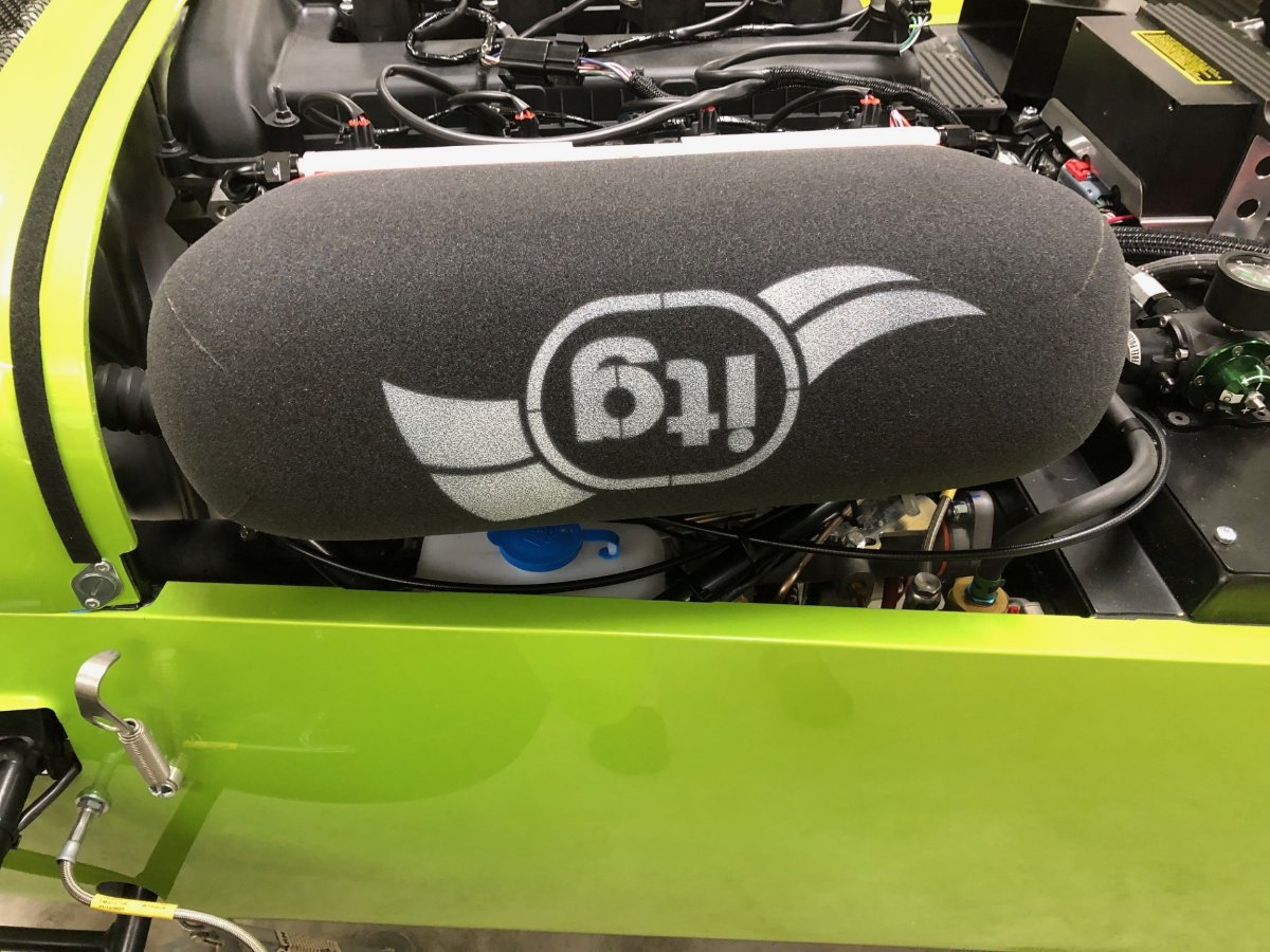
Those with better memories than mine may recall my initial plan was to build a cold air box fed by the intercooler scoop in the 620 nose cone. Space challenges and concerns that the amount of air reaching each cylinder could differ significantly given the limited space available for the cold air box, led me down the path of that old standby: a sausage filter poking out of the bonnet. Cutting the filter hole on the Westfield wasn't too hard given the bonnet is fiberglass; Get the hole reasonably close, then use a Dremel to carefully expand the opening until it's the right size and shape. The Caterham's painted aluminum bonnet, however, seemed like a bigger opportunity for screw ups. Let the anxiety begin... First step was installing the filter and marking its location in relation to the bonnet with a combination of strings and marker lines on the side skin. Chip board (cereal box material) was then fashioned into a partial bonnet, and the strings and marker lines were used to draw a rough, slightly oversized representation of where the filter would poke through. That section was cut out, the air filter was reinstalled, and the gaps to the filter were taped over then trimmed to shape. Next, the filter was removed, the bonnet installed, the chipbopard template laid over the top, and the shape of the cutout transferred to blue tape on the bonnet. This is where things got scary. A rough cut was made with an air saw, then began an iterative approach of fitting the bonnet, marking where more material had to be removed, then using either the air saw, files, or a 60-grit flap wheel in a drill to make those adjustments. Finally, some rubber edging was used to seal the cut edges. Next step is a test drive. -John
-
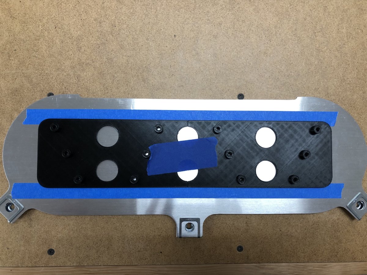
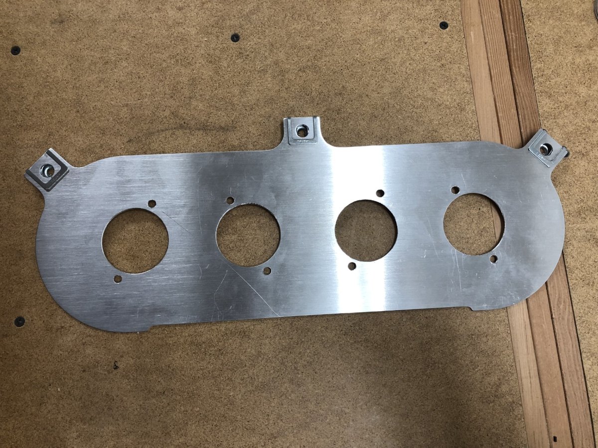
The front wheels have been rebalanced on a Hunter Road Force machine. According to the shop, some wheels have a slick-ish coating that must be cleaned off to avoid the weights falling off. Apparently neither Caterham nor my dealer's shop cleaned them well enough. I'll need to keep an eye on the rears to make sure those weights stay in place. The filter with logo arrived on Thursday. First step was drilling the baseplate for the Jenveys. One reason I chose the ITG over the Pipercross used on the Westfield, is the mounting system. The extra height of the 2.4L, means mounting either brand right side up would place the 1/4 turn fasteners very close to the bonnet. To eliminate any possible rubbing issues, my plan was to mount the filter upside down (one of the reasons I special ordered a no-logo version). The bottom portion of the ITG mount is cleaner looking and more compact than the Pipercross. Since that would be the top in my installation, I went with the more compact design. A drill template for the various holes was printed to ensure that portion went well. I still need to add 2 more holes for the air temp sensor but wanted to do that last since I knew room would be tight and I wanted to have the baseplate in place to figure out the location. -John
-
Driving with no center console: reduced buffeting?
JohnCh replied to TurboWood's topic in General Tech
@TurboWood have you had a chance to test this yet? Thanks, John -
Yes on both counts. Mazda founded the site in 2005 and drove a V8 Rotus named Frankn7.
-
yep, just wanted to call that out in case you were going to give that a shot. I forgot that you mentioned the Banner is doing the same thing. It's unlikely you have two duff batteries, so ignore my comment. Given the Banner is back in place, and you have the voltage drop info when cranking with that battery, maybe reach out to Caterham's build support alias and ask if that is an issue? They might have some troubleshooting ideas. I've found that Lee is helpful with oddball questions.
-
One thing to be careful of is that Antigravity specifically states not to use it in conjunction with a normal battery. Relevant section from the user manual: "COMPATIBILITY. The product is only compatible with 12-volt stock systems in vehicles. Do not attempt to use product with any other types of batteries or in series or parallel with another battery, or interior electronics could be damaged. Use with, or Jump starting other battery chemistries may result in fire, explosion, injury, death or property damage. Contact the battery manufacturer prior to attempting to jump start the battery. Do not jump start a battery if you are unsure of the battery’s specific chemistry or voltage." You're using the stock cables, so they should be more than sufficient. If it is wiring related, it could be a damaged wire or a poor/dirty connection somewhere. I'd go through the entire system, including the battery disconnect, with a multimeter and see if resistance is higher than expected at any point. Another possibility is a duff battery. Might be worth asking AG. -John
-
Thanks to @Christopher smith, this is now live in the Downloads section: