JohnCh
-
Posts
3,406 -
Joined
-
Last visited
Content Type
Profiles
Forums
Store
Articles
Gallery
Events
Library
Everything posted by JohnCh
-
Wow is right! Do you have dyno curve you can post? Did they use an exhaust manifold dimensioned similarly to yours when they did the test? Thanks, John
-

The Regular Summary of Classified Ads of Se7ens Found For Sale
JohnCh replied to Croc's topic in Cars For Sale
You realize you just described driving a se7en, right? -
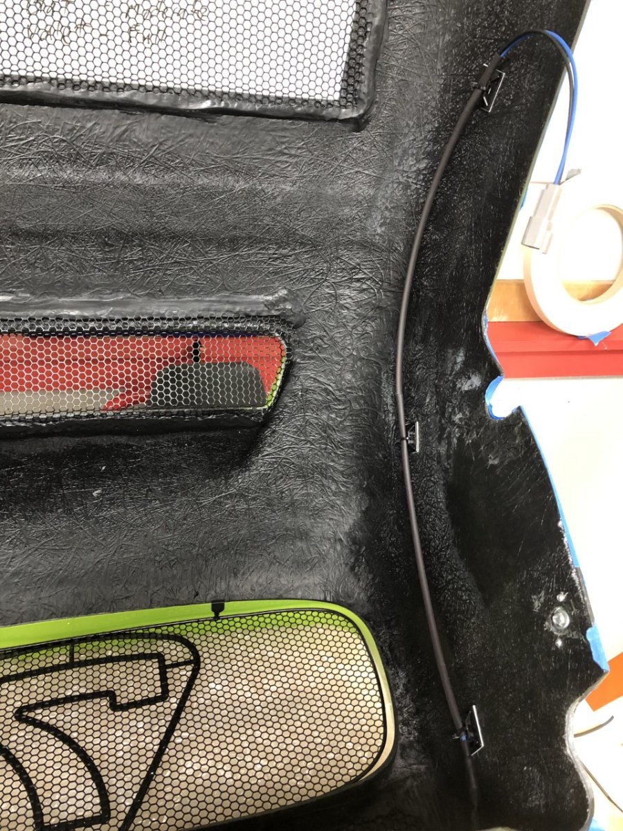
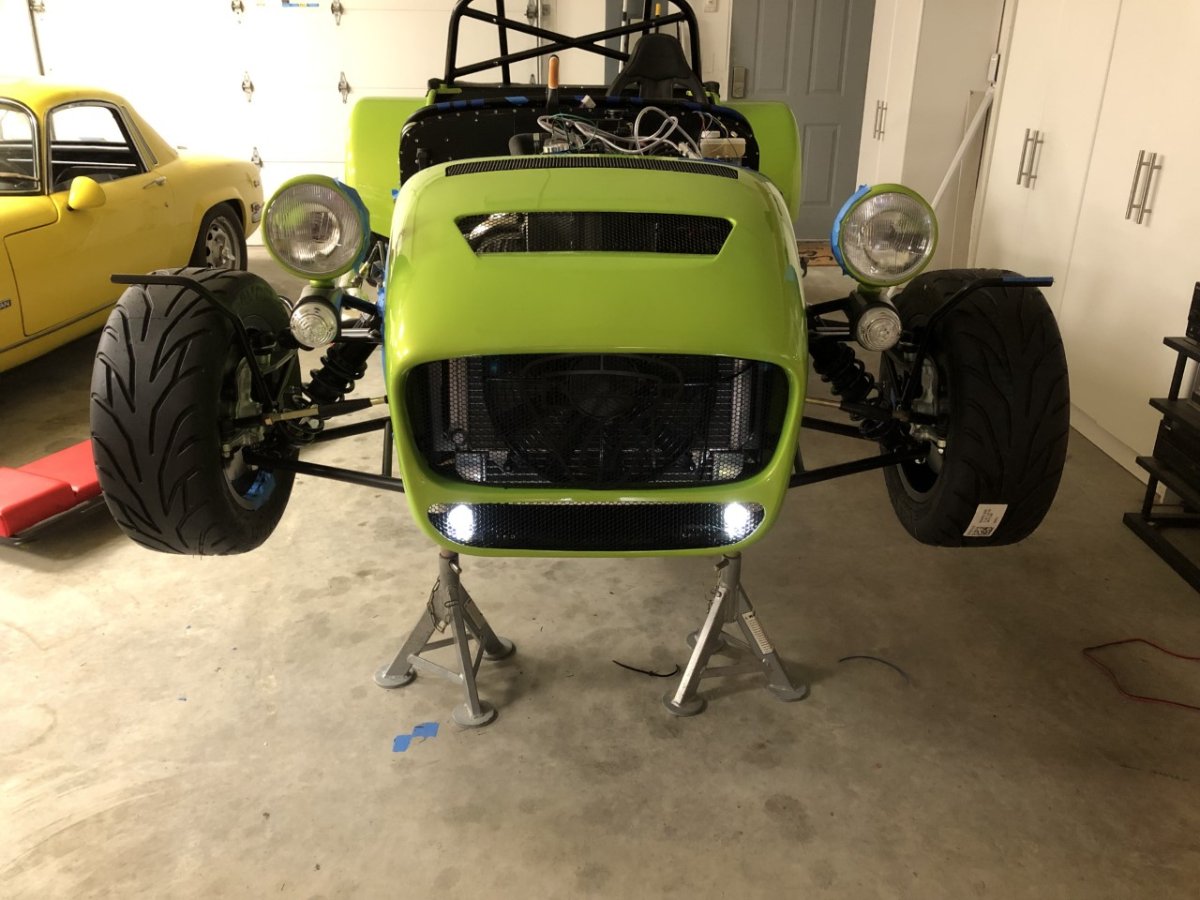
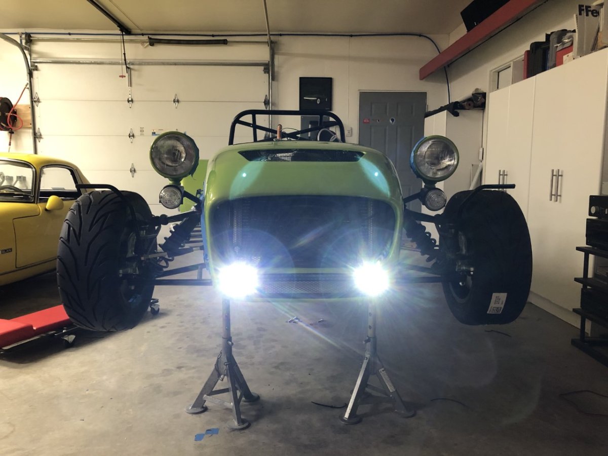
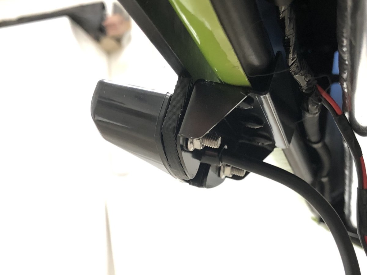
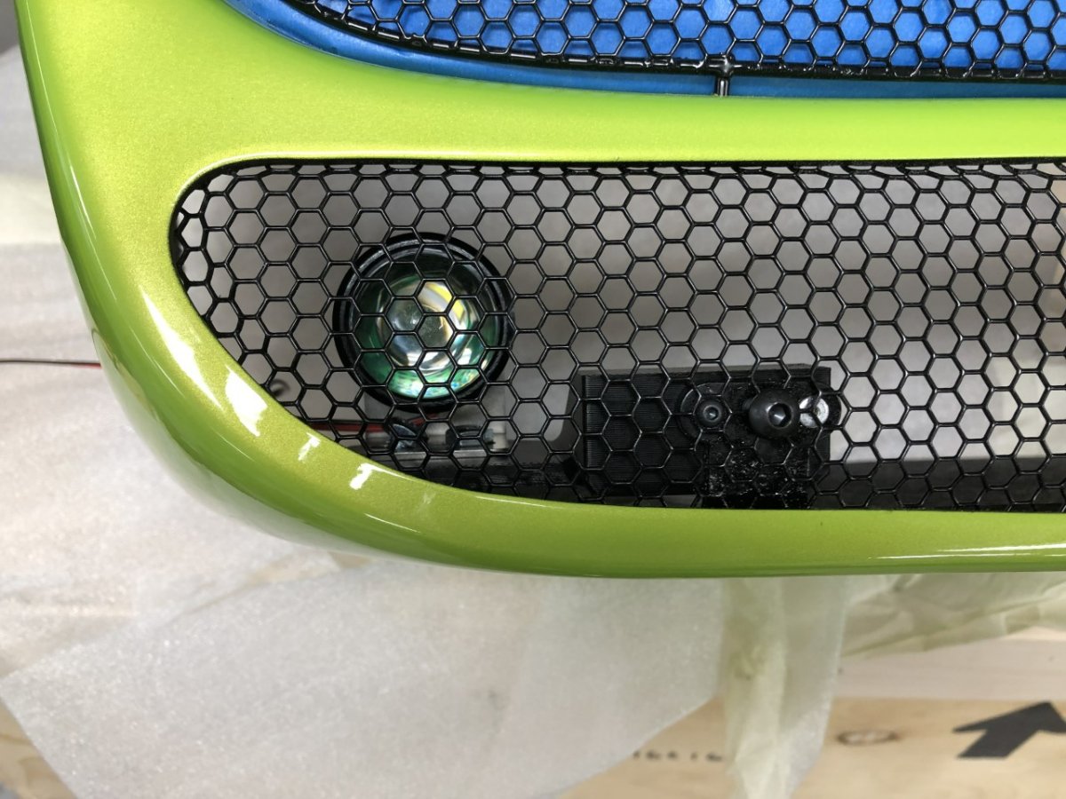
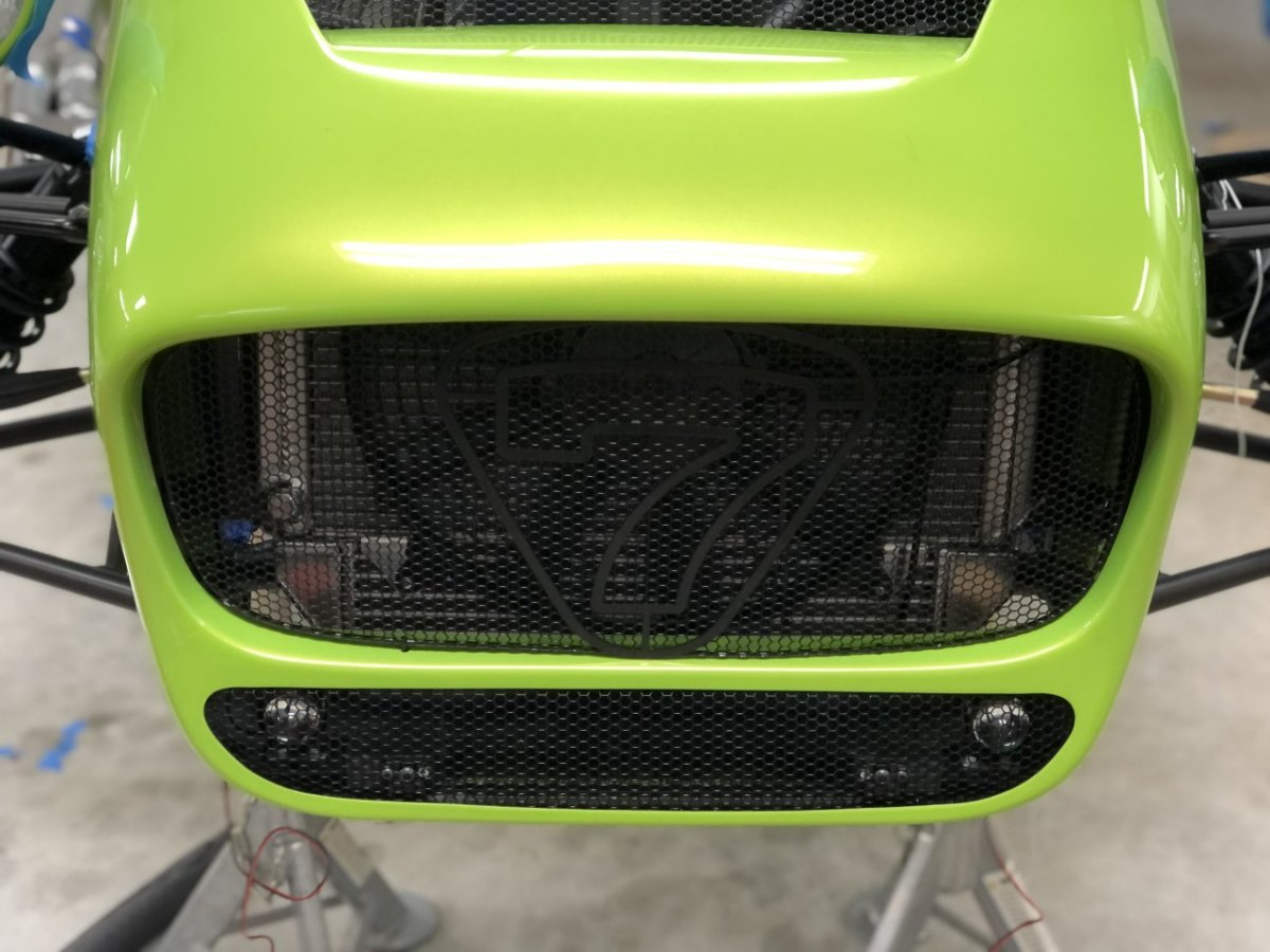
I decided to do a temporary install of the DRLs so I could build the harness and get that out of the way. This is the redesigned bracket. Very rigid but will need to be reprinted in carbon fiber nylon to deal with the heat from the radiator. Hoping to do a big print day this weekend to get all parts done using that filament. The wires were run under cover of the license plate bracket the factory glued into the nose cone, then run up the side using adhesive zip tie mounts and finished with a Deutsch connector. I decided to place this on the exhaust side since there is more room on that side of the engine bay. It's very easy to undo the connector before removing the nose cone. These guys are pretty bright. First photo is taken off axis to highlight the location. Next photo is head on. Speaking from experience, I don't recommend looking straight at them from only a few feet away -John

-
I run the Racetech mechanical gauges (coolant and combined oil temp/pressure) in my Westfield. The size of the temperature sensors is a pain, but not an issue if just using oil pressure. No complaints after nearly 20 years of use. -John
-
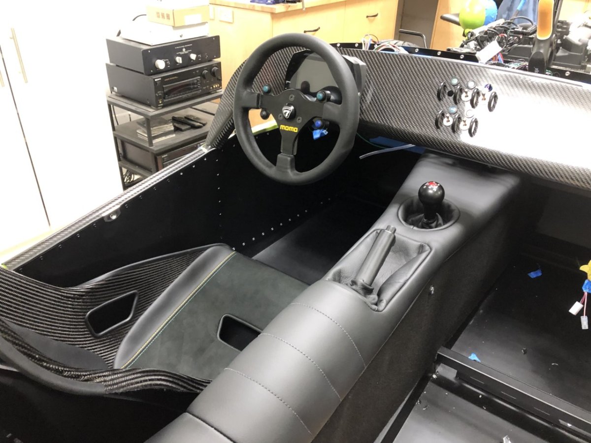
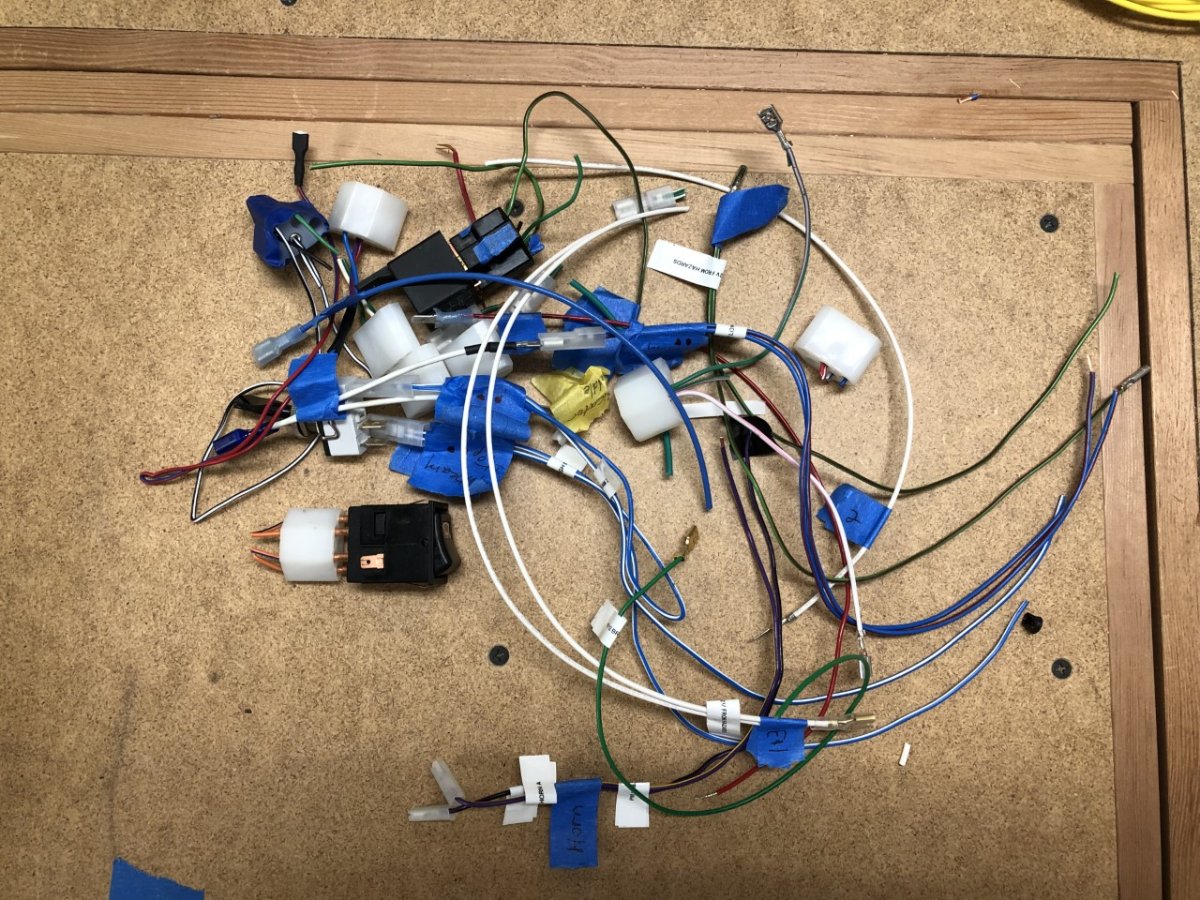
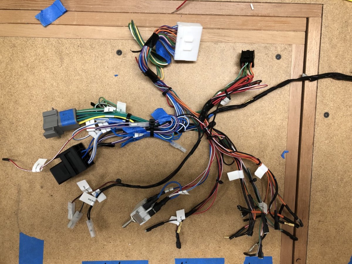
A few days ago, I wrote "If things go very, very well (they won't) the AiM and Freewheel wiring could be completed this weekend." Well, they didn't go very, very well, but things still went well, if not very well. The Freewheel chassis wiring is done, and it works. The final switch plate for the steering wheel hasn't been printed as I'm working through a couple of cosmetic revisions, so I simply shorted the transmitter wires, mimicking momentary switches. A little troubleshooting was required, but nothing onerous. I'm opting to keep the labels on the harness in place as well as some unneeded wires until the AiM harness is done and the combined harness is tested. Top photo shows items removed thus far, and the second shows the current state of the harness as described above. Rather than use Weatherpack connectors to tie the 14 wires from the Freewheel control module into the rest of the switch loom, I bit the bullet and bought a good crimper for solid pin Deutsch connectors. It was so much easier and less frustrating than the stamped terminals used with Weatherpack. When given a choice, I will never go back. One annoying discovery is that when upgrading the tunnel cover to the black leather version in the Signature catalog, they don't bother to install the heated seat switches, instead supplying them in a bag with the retrofit harness that isn't needed when the heated seats option is chosen at time of order (once again, Caterham supplies parts you don't need, which apparently they karmically believe offsets failure to supply parts you do need -- but I digress.) It sounds simple, but this is upholstery work in a highly visible place. It requires drilling holes, cutting the leather, wrapping it through the holes, gluing it to the aluminum structure, and hoping the resulting hole is sized perfectly for the switch. Not too small that it won't push in, and not too big, that it rotates with little effort. Not wanting to see my potential screwup every time I looked at the interior, and not really being a fan of the switches breaking up the aesthetic of the tunnel top, I took this as an opportunity to relocate them to the side of the tunnel. After determining a location that was easy to access, wouldn't be accidentally bumped by errant knees, and was sufficiently removed from the multitude of cross braces in the tunnel, holes were drilled, the carpet was installed and then cut. I like it. I also did a bunch of other work, including rerouting the handbrake cables, fixing the buggered rivnut for one of the rear wing bolts, working out the DRLs, identifying the wires in the gauge loom and how they will plug into the AiM analog harness, and a number of other little things. Not the massive progress I hoped for, but more than I expected. Before calling it a night, I installed the tunnel cover and steering wheel, and tried out the seating position. It's getting there... -John
-
Link is fixed. When you inserted it, it added the word "My" at the end, likely from when you copied it. I've removed, that unnecessary appendage -John
-
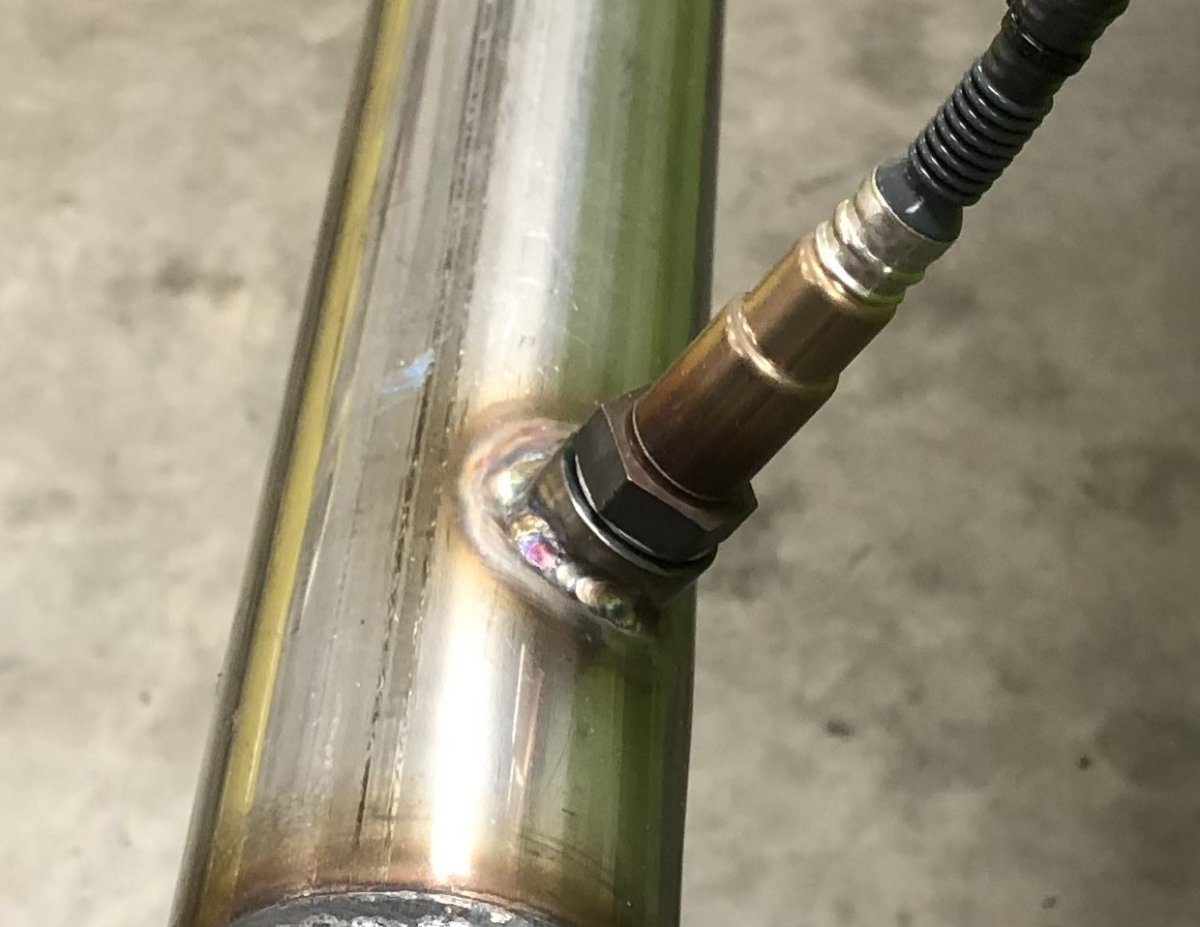
One surprisingly hard part of this project was finding someone to TIG weld a stainless steel WBO2 bung on the stainless steel cat bypass pipe. The factory bung locates the sensor so it's pointing upwards, which is bad for longevity. Ideally the sensor should be mounted at least 10 degrees above horizontal to prevent condensation from settling on the tip and breaking the sensor after a cold start. It seemed every place I called only did MIG and every lead I was subsequently given would have the same limitation when called. I eventually found three places. A very high-end vintage race shop in the Kent/Auburn area who dismissed doing the project out of hand as too small, a high-end race shop in Bellevue, and a family-owned welding shop located next to an airstrip in Snohomish that's been around since 1972 and does everything from building custom exhausts to installing 5th wheel hitches. The race shop said it would take 1- 2 hours at $225/hour and they couldn't get to it for at least a month. In contrast, the welding shop wanted $58 to drill and TIG and could turn it around in a day. I went with the family operation and was very pleased. Friendly, clearly take pride in their work (even the person who did the weld wanted to make sure I was happy with the final quality), and very reasonably priced. Anyone in Seattle's Eastside looking for this type of work, check out Airport Welding and Muffler in Snohomish. -John
-
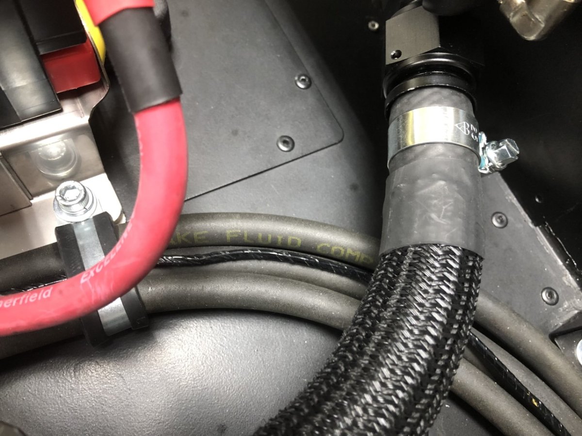
I used heat shrink to hold down the ends of the mesh cover on my coolant hose. -John
-
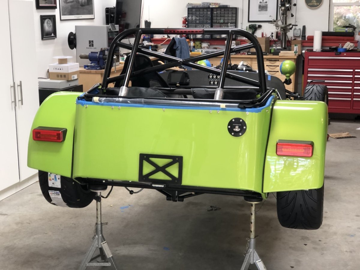
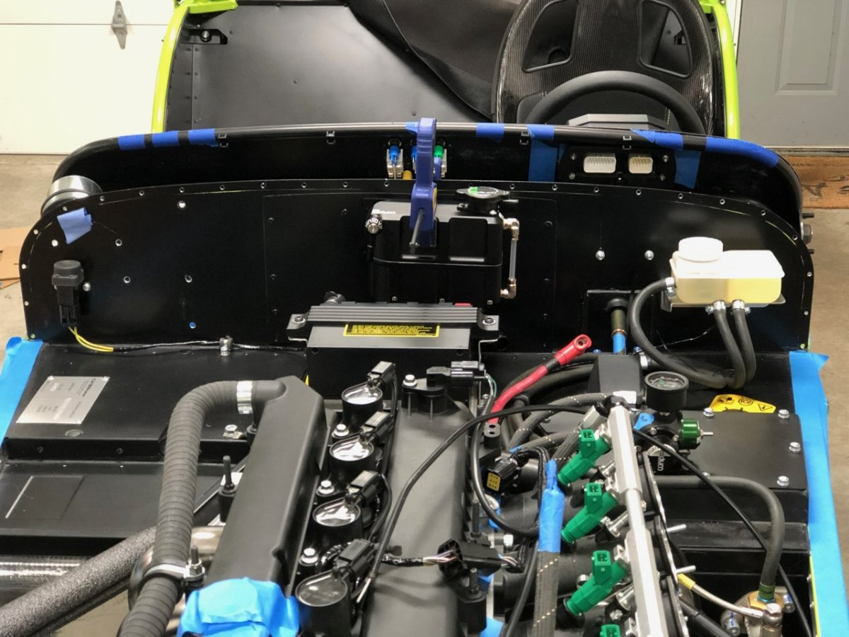
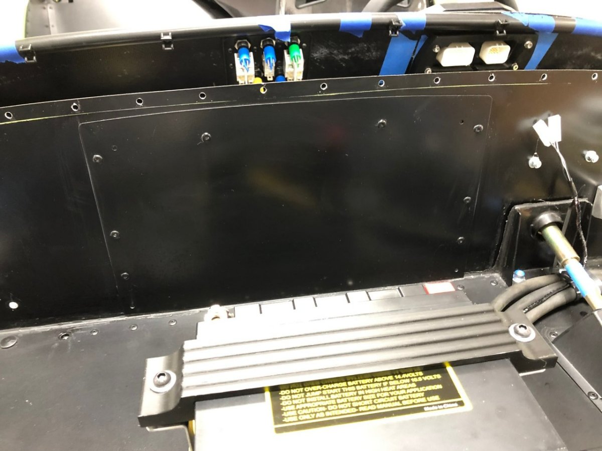
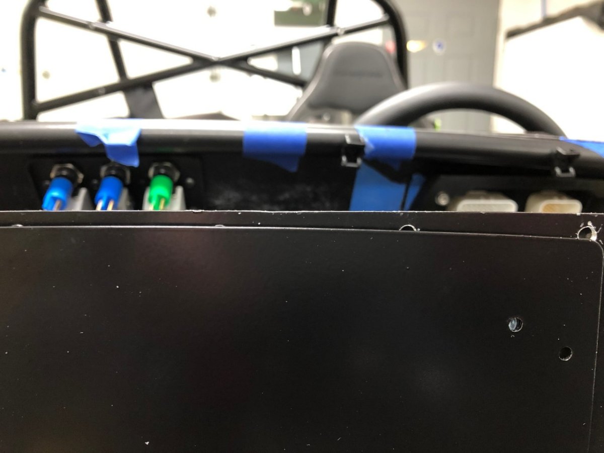
The underside of the wings have been coated with Herculiner to prevent star cracks. I was initially on the fence about this as the Westfield wings have suffered no such damage since going on in 2004. A closer look, however, revealed Westfield uses much thicker fiberglass. Based on quick measurements, the Caterham wings are about 3mm thick, whereas the Westfield's are over 5mm thick. Undoubtedly heavier, but I suspect this is why I haven't had issues. Rear wings are on, but the driver's side needs to come off to inspect a rivnut that I suspect may be a little loose. Of course it was the last of the 10 fastener I installed on that wing. I'm currently in wiring hell. Despite attempting to order the 620 switch loom since November, I've given up and am repurposing the 420 switch loom. Before making cuts, I decided to reinstall the stock dash with the gauge and switch looms to confirm all those electrical components are working correctly. This way, if an electrical issue crops up for the AiM, Freewheel, or toggle switches, I'll know it's my fault and won't need to test any of Caterham's work. Once an issue with the factory supplied flasher was confirmed, it was time to perform a test install of the Freewheel without cutting the harness. I wanted to wait for that no-going-back moment until I knew the Freewheel worked as expected. Yes, that's a scary picture below, but it was taken after achieving success with the test. I'm now in the process of modifying the switch loom -- wires have been cut! -- and will then tackle the loom for the AiM display. If things go very, very well (they won't) the AiM and Freewheel wiring could be completed this weekend. -John
-
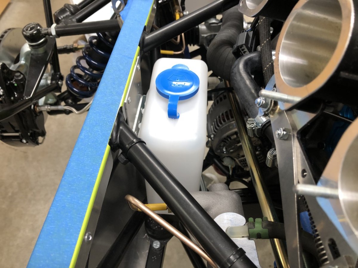
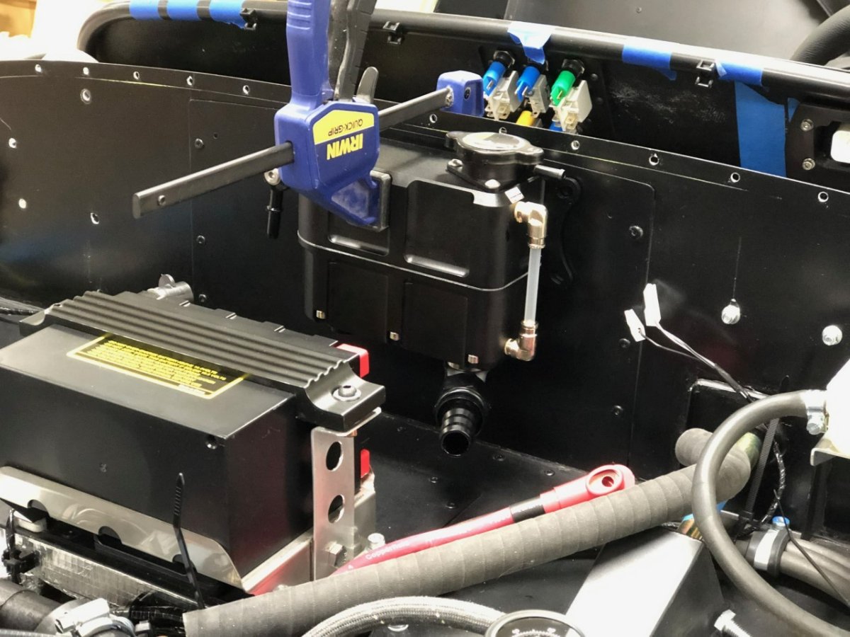
The Radium coolant expansion tank is in and plumbed with a hose covered with nylon braid to provide a little more abrasion protection where it runs into the mass of hoses in front of the battery. I also plumbed the cooling in that area with correctly sized 3/4" hoses. Because I am not using the second coolant temp sensor that feeds the gauge, I don't need the submarine which is 5/8" diameter, and is my guess for why Caterham supplies the smaller hoses (see my rant about this several posts up the page). I ended up using a combination of rubber hoses and Silicone hoses given availability. We'll see how it works. The location for the windscreen wiper reservoir on current cars is in the boot, which is not my preference. Taking up valuable real estate in the small boot to locate a container of liquid does not make a ton of sense to me. To be fair, the factory 420 air box takes up a lot of space, so finding an under-bonnet location means they would need to be creative or use a different form factor, but still… My initial plan was to locate this part on the firewall. However, given I'm running ITBs with a sausage air filter, another option presented itself: under the filter. A simple aluminum bracket to dop it a few inches that repurposes two rivets that hold the side skin to the frame, and it's in place. It does mean I need to remove the air filter to fill it and work round an air horn, but the filter attaches with three 1/4 turn fasteners, and even if I have to remove the air horn (two socket head screws) it's not a big deal to me as I will likely only fill it before a tour when there is a chance of rain. Otherwise, I won't use it and won't bother it keep it filled. The scuttle is now removable to make behind dash repairs/work significantly easier. To minimize the air gap between the firewall and scuttle, low profile M4 rivnuts from McMaster Carr were used. These have a flange thickness of 0.4mm vs. 0.8mm of a standard rivnut. The only challenge was installing the rivnuts that mount to the dash tube and hld the sides of the scuttle in place. On my car -- and it may only be my car -- they drilled the hole for the rivet at an angle pointing rearward rather than forward as needed to place the hole perpendicular to the side of the scuttle. When using a rivet, the hole angle doesn’t matter, but a rivnut is a different story. Given it's a round tube, you can't simply enlarge the hole in one shot and need to walk up on it with increasing larger drill bits. Ok, no picture, but if you look at the photo of the Radium you can see the rivnuts in place. -John
-
Wow, this thread is way out of date. I'll try to post some updates with pictures later. Regarding the airbox, the original plan was to build a cold airbox fed by the 620 nosecone scoop. I eventually gave up on that for two reasons: space and potential AFR issues. Between the dry sump tank and its hoses, the coolant hoses, and the chassis triangulation, there is not a lot of space to snake sufficiently large ducting from the front to the throttle bodies. It's solvable, but it just creates more problems down the road with access. More importantly, I found some flow tests on airboxes that convinced me there was a reasonable chance AFR across the 4 cylinders would be very uneven. A single WBO2 sensor would average out those differences when tuning, meaning some cylinders could be overly rich, or worse, overly lean. It seemed much safer for the engine if I bit the bullet and stuck the filter out the bonnet; nose levels be dammed! Cutting the aluminum scares me but blowing that engine scares me more. That work is still about a month out so I can't tell you how not to do it . I special ordered an ITG sausage filter without the logo and was told to expect arrival in April or May. Based on results from online calculators, the bonnet side vent is sufficient for 420 levels of power. Those same calculators say the 620 shouldn't work, but it clearly does. Perhaps those formulas change with a supercharger, or there is more going on with high pressure in that area that offsets the size of the opening. That said, I also noticed that the opening in the air box itself is smaller than in the bonnet, but again, it seems to work. -John
-
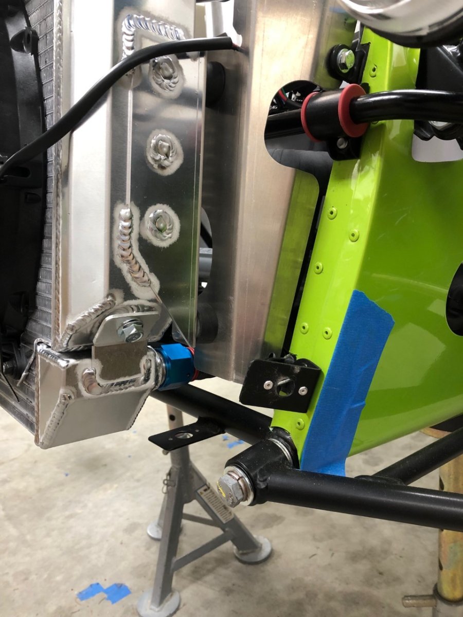
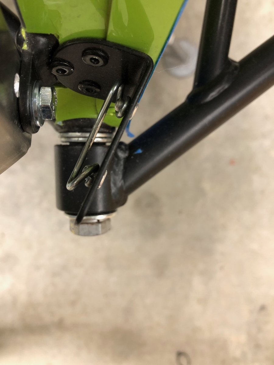
Here are a couple of pictures of a lower 620 nose cone mount. The first shows the location near the lower radiator mount, the second is an overhead shot that highlights the angle in relation to the lower A-arm's front mounting bolt. -John
-
There is a slew of filament types, each with different strength, impact resistance, UV, thermal, and chemical resistance properties. There are even differences between brands for the same filament type. To further complicate matters, some filaments require more specialized printers that can handle the high temperatures required to melt that filament or can heat the bed or the enclosure to specific temperatures or maintain more stable temperatures. Some filaments are also a lot more finicky to print than others, requiring more experience to produce a quality print. This page has an overview of the more common options that might prove interesting. https://www.3dsourced.com/guides/3d-printer-filament/
-
Thanks, I'll keep them in mind if I need to print a file beyond the capabilities of my printer or if I want to try the part as an SLA print.
-
It would never have occurred to me to go down that route, but it looks great. How was your experience with craftcloud? Thanks, John
-
Interest in a 3D printing or fabrication forum and Downloads section?
JohnCh replied to JohnCh's topic in Forum Evolution
The new forums are live. Post away! -John -
Interest in a 3D printing or fabrication forum and Downloads section?
JohnCh replied to JohnCh's topic in Forum Evolution
I'll try to add the new forums this weekend. We'll have a header under the Technical section called Fabrication with two forums beneath it: 3D Printing, and General Fabrication. The latter is intended for everything from metal work to composites. -
The flex was my original concern, but after testing the initial print, I don't see it as an issue. There is a surprising amount of space for it to flex without touching, and if I stick with this route, I'll print out of carbon fiber nylon which increases rigidity. I'll also add rubber bumpers near the bolts with PPF behind the bumpers just to be safe. -John
-
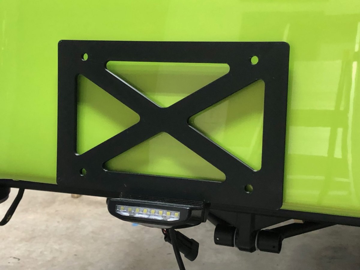
Here is a close up of the mount taken from under the car looking toward the back. The reverse light bolts go through the plate holder then through the holes on the chassis mount. Easy to replicate something similar from aluminum. -John
-
I'm playing around with something like this that attaches via the reverse light mounting bolts. My 3D printer will only do 10" wide vs. the 12" width of a license plate, but it is wide enough. -John
-
Good Caterham mechanic in Virginia or mid atlantic?
JohnCh replied to Saudio's topic in General Sevens Discussion
Chip Bond at GT Classics in Barboursville has been working on Caterhams for years and has a great reputation, particularly when dealing with the hard stuff. I'm not certain he is still active or if has retired, but his webpage with phone number is still up: http://www.gt-classics.com/ -John -
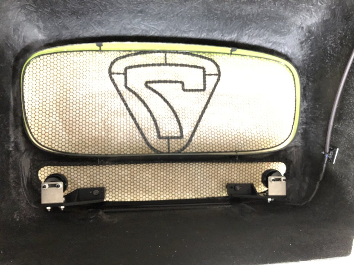
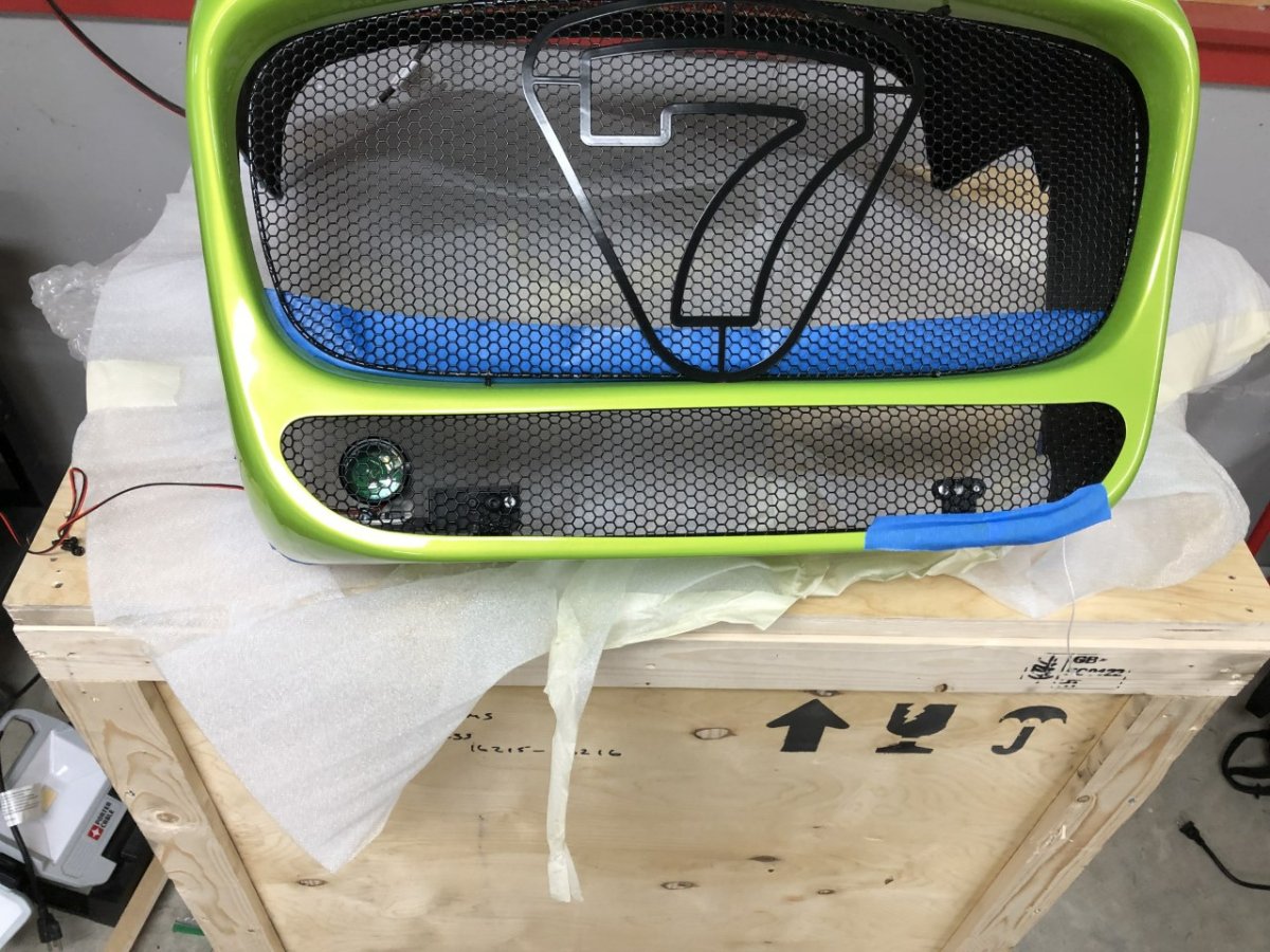
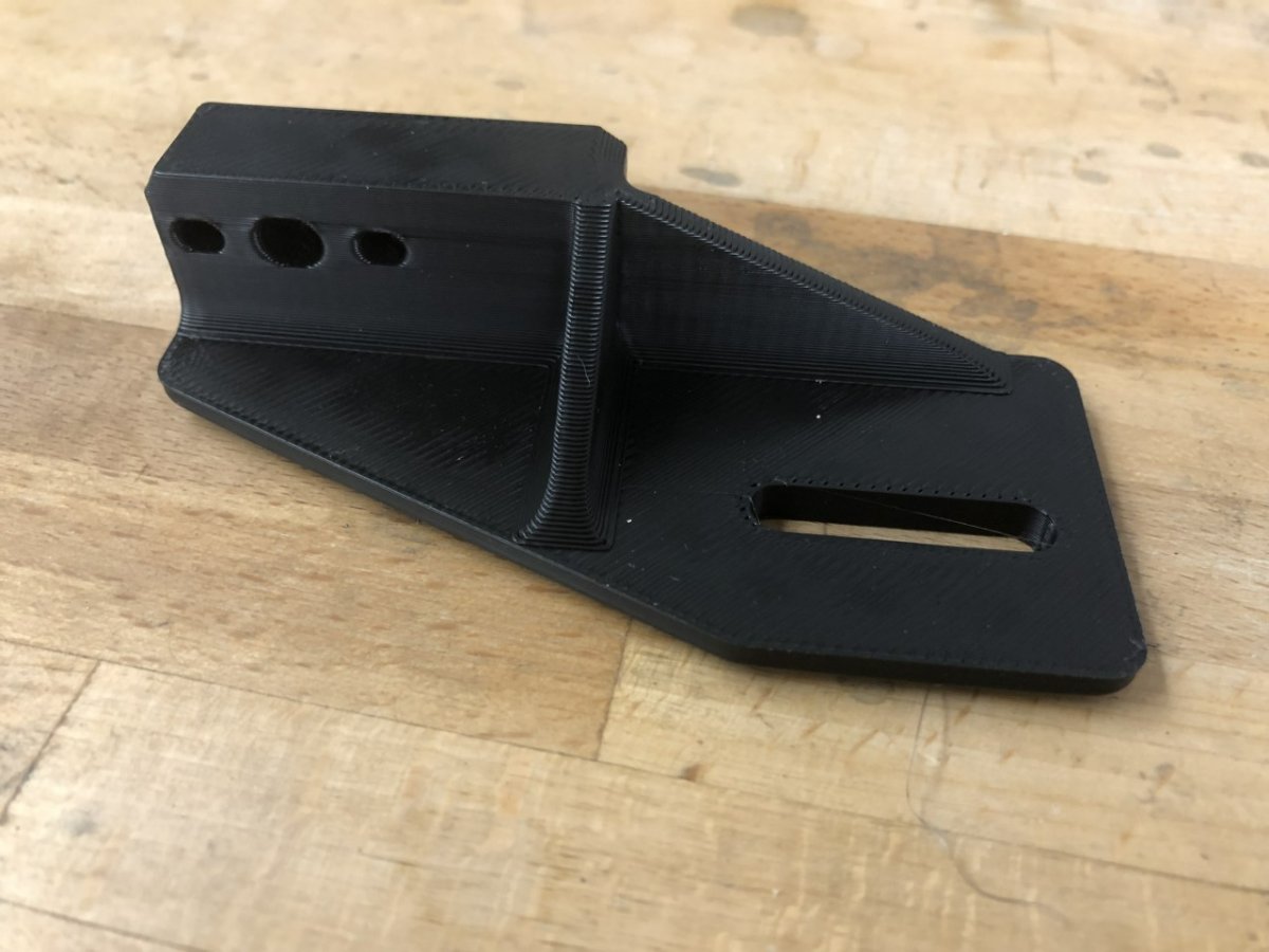
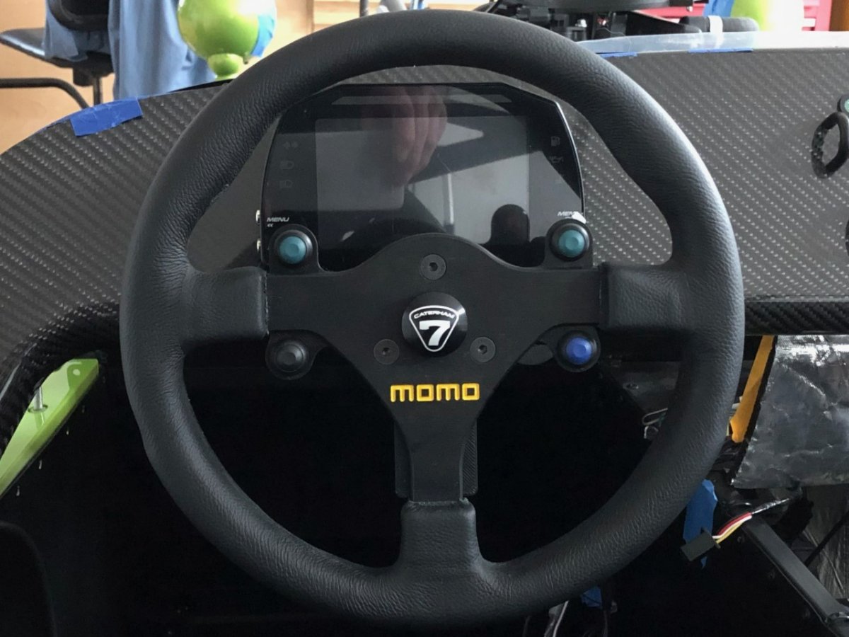
Next up was progress on the DRLs. The 620 nosecone has a Euro sized license plate bracket glued into the bottom that I repurposed for DRL mounts. Simply drill out the 1/4 turn fastener nuts, bolt on 3D printed brackets, and attach the DRLs. The pic of the 3D printed part shows the final version, which differs slightly from the version used in the other photos (an extra rib and some cosmetic chamfers.) The laser engraving on the horn button is finally done. Other than a smeared E, it looks good. -John
-
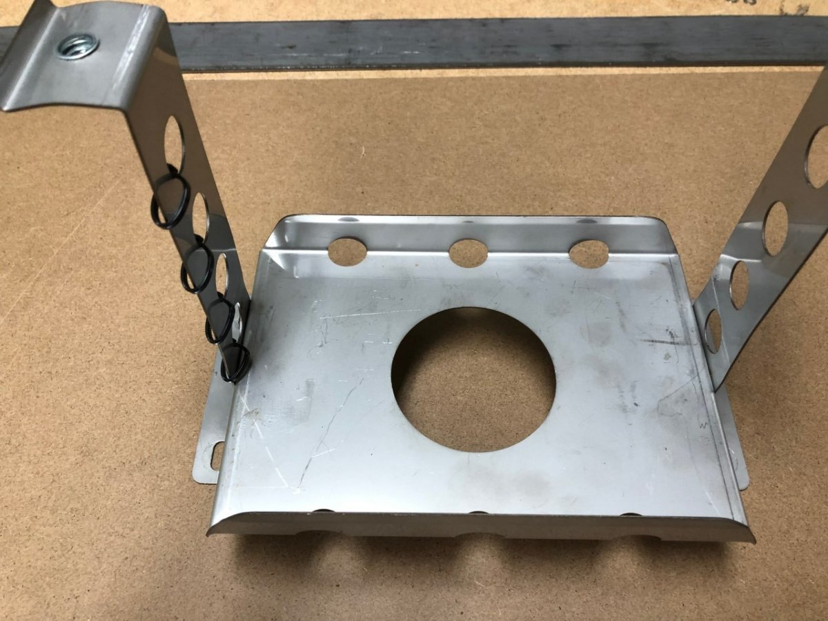
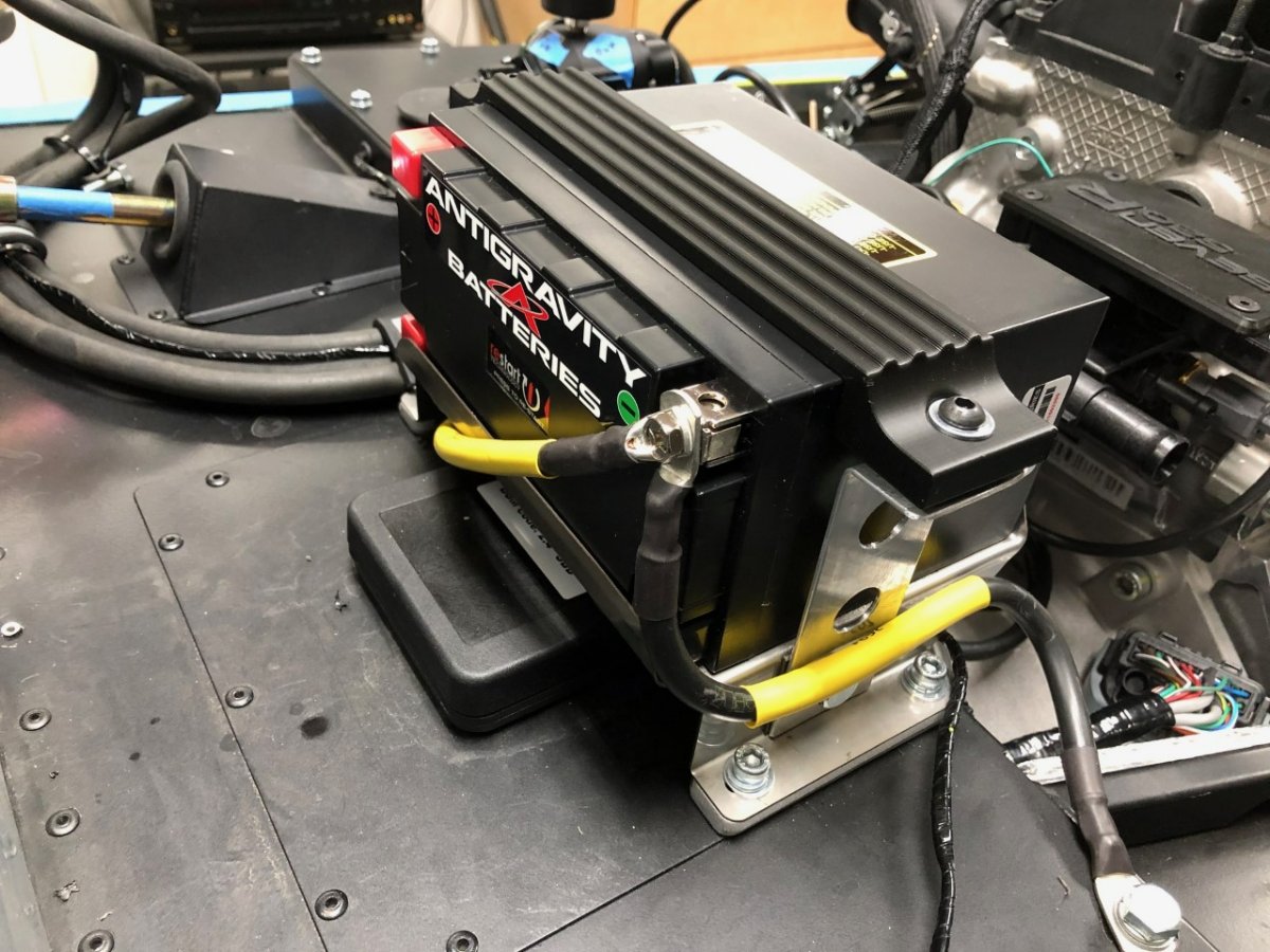
The Antigravity Lithium-Ion battery doesn’t fit the factory battery holder, but it seemed a shame to toss the stainless steel base that fits over the ECU. Rebending the rear lip to accommodate the extra length of the AG battery when on its side, then replacing the side straps with shorter aluminum versions and 3D printing a new top clamp, it fits well. I just need to print spacers to fill the gaps between the side straps and the battery. According to the scale, the lithium battery saves over 11 pounds which offsets the weight gain from the bigger engine. BTW this was my first time trying to bend or drill sheet stainless steel. Wow, this is a hard material! About this time, I discovered my kit included the correct number of battery cables: three. Kudos to the QA person for their counting skills! Counting all the way to three can be hard!. Unfortunately, rather than supplying one red positive cable and two black ground cables, my kit came with three ground cables. Apparently counting to three is much easier than differentiating between the colors black and red. Since I am mounting the battery slightly differently than factory, this served as an opportunity to correctly size a new positive cable for my installation. The factory all SS battery holder: The replacement for the smaller battery: -John
-
Firewall cleanup has begun. With no need for the factory airbox, the brake/clutch fluid reservoir was moved to that side, freeing up space to mount the fuse box so it pokes through the firewall, making it easy to change/check fuses and relays. The factory positions this on the back side of the firewall under the scuttle and requires a contortionist to check. In my experience, a fuse is most likely to blow on a rainy night in a dimly lit parking lot. This new position will make those situations far less frustrating. I'll wait to cut the firewall until I finish the under scuttle electrical work to ensure it's optimally positioned. One surprise -- OK, not a surprise, I'm used to looking at aspects of this car and asking no one in particular what the hell the factory was thinking. Anyway, one surprise was the heater block-off plate. The firewall has a large section removed for the heater box. When no heater is optioned, that opening is covered with a block-off plate during the build. There were a couple of problems. First, they size this plate so the top covers a portion of the scuttle rivet holes. Since I am doing a removable scuttle, this is problematic. Second, and the part that made me mutter "Um……" the plate has a number of drilled holes that match up to the mounting holes drilled in the firewall. It makes sense for the factory to reuse the mounting holes, right? Except they drilled the holes in the plate for 1/8" rivets which are juuuust a bit smaller than the firewall holes drilled for M6 bolts. Fortunately, the fix for both issues was cutting 15mm from the bottom, then drilling new holes in the firewall to match the 15mm lower holes on the plate. -John
-
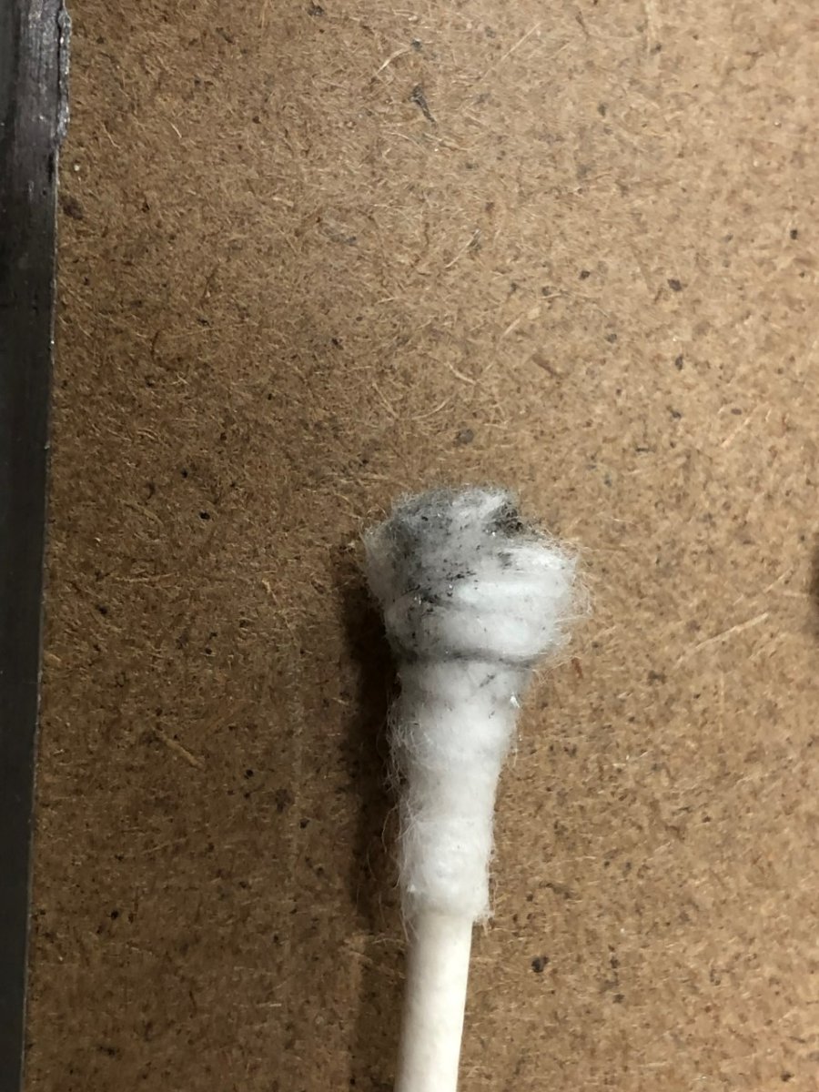
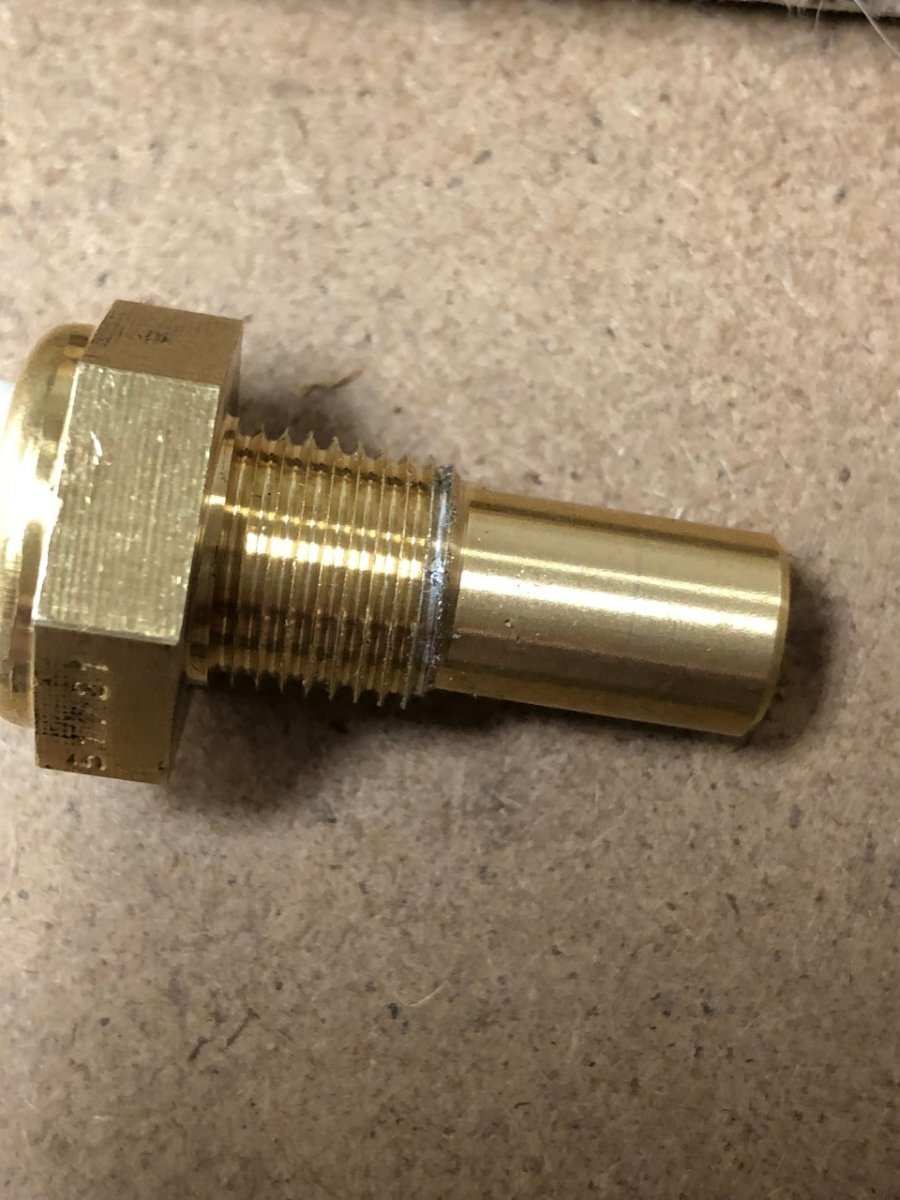
Attempting to install the oil and coolant plumbing was fun due to product quality issues. First, unbeknownst to me (i.e. user error on my part) there are two versions of the rear coolant junction that bolts to the back of the Duratec's head. One has a port for the coolant temp sensor that feeds the ECU and the other has that port blocked off. I purchased the wrong one months ago but didn’t discover this until trying to install the sensor. The replacement arrived, but it had a manufacturing fault that prevented the sensor from seating. The third one was the charm. Turning to the dry sump plumbing, I discovered the oil tank arrived with a poorly threaded 1/8 NPT port for the temp sensor. First the threads were full of aluminum shavings, and second, the sensor blanking plug and sensor could only be screwed in 1/2 turn by hand. Using a wrench to turn the sensor a further 1/2 turn cut a groove in the threads. Bruce Beachman had me bring the tank to his shop so he could run a tap through it, but quickly discovered the tap was actually a little loose. The theory was the first thread had a little damage at the beginning from the factory screwing in the tapered tap too far. My sensor was still a little off when attempting to screw it in after the cleanup, so Bruce switched to a spare which screwed in better. It was still hitting a spot of increased resistance in part of the thread, but it was far less than with my original sensor. With both of those sorted, most of the plumbing was installed. Rather than use the factory coolant expansion tank which mounts under the nosecone where access requires nosecone removal, I'm using a Radium Engineering expansion tank mounted to the firewall. On the positive side, it looks great and is easy to access. The negatives are an additional 1-1/2 lb of weight and a stupidly large price tag. My hope was to finalize the install this weekend, but then I discovered Caterham supplies 3/4" ID hoses for the dry sump breathers but supplies 5/8" ID hoses for the coolant plumbing. This isn't an issue for the 5/8" metal tube they supply which houses the coolant temp sensor for the dash gauge, but it is an issue for the connectors Ford uses on the rear coolant junction and water pump which are both 3/4". Interestingly, Caterham supplies a T-connector to plumb the expansion tank and this too is 3/4". For the heck of it, I lubed up a hose and the T-connector to see how hard it would be to seat, and more importantly, how hard it would be to remove. It took a little effort, but it would seat. Removing it was another story. It was simply not feasible without a hose pick and even then, it was difficult. Not sure I could do this with limited space in the car. More worrying was the outer barb of the T-conne ctor made a cut along the inside of the hose. It was not subtle and didn't give me comfort for longevity. I'll order properly sized hoses this week. -John