JohnCh
-
Posts
3,406 -
Joined
-
Last visited
Content Type
Profiles
Forums
Store
Articles
Gallery
Events
Library
Everything posted by JohnCh
-
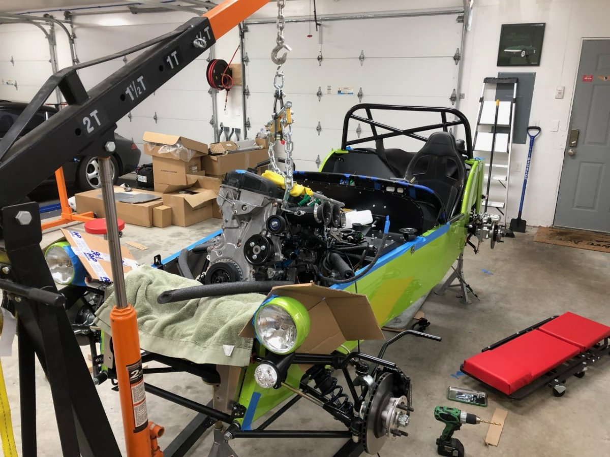
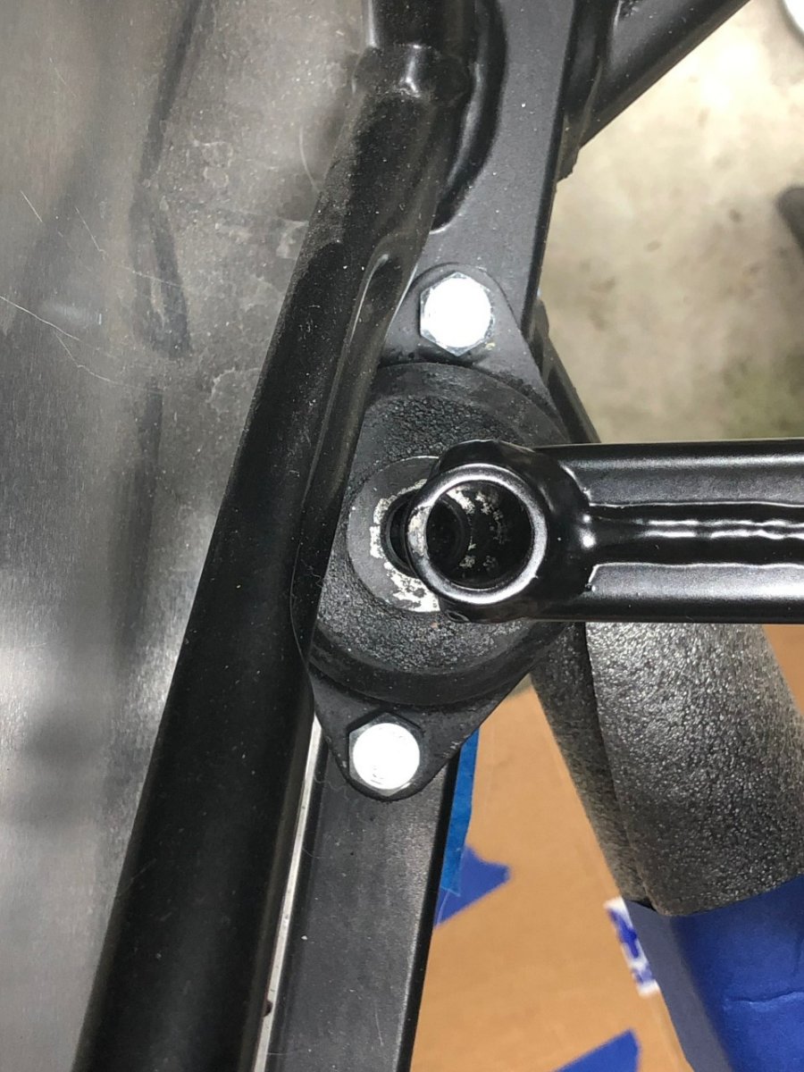
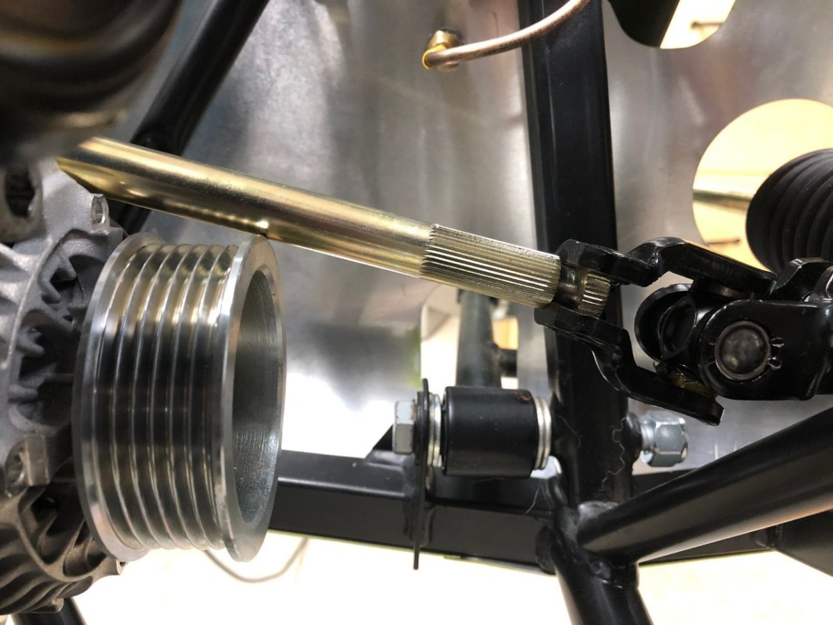
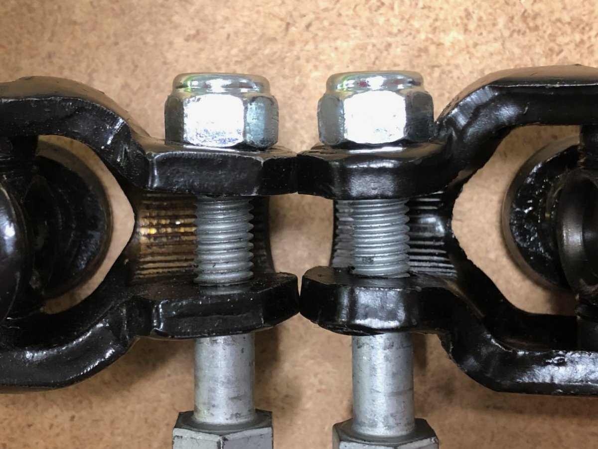
Progress has been slow thanks to other priorities getting in the way and some level of procrastination born from frustration with the car, some vendors, and a realization that some things I had planned were too much effort to achieve during the initial build. There are, however, a number of updates. I'll break them into a few posts, but don't worry, I promise to sprinkle a little bitching and moaning into each one. The engine and transmission are in. I've removed and replaced the Duratec in the Westfield a few times over the years. I've always done it solo and without a load balancer. It's a pretty straightforward process. Not so with the Caterham. Clearances in this car are extremely tight. The process was made more challenging by the fact the rear suspension and driveshaft were already in place, and I opted not to drain the factory installed oil from the gearbox. I'm not convinced I could have done the job solo without the load balancer. It also took more swearing than I'm used to, but that extra effort certainly helped. After confirming crank and chassis centerlines aligned, the driver's side engine mount had to be shimmed 4mm away from the block. Next hurdle was the alternator getting in the way of the steering shaft. The solution was easy (although someone else had to point it out to me): rotate the steering rack forward to raise the u-joint and steering shaft. I'm not sure if this need is down to more production inaccuracies or if the taller 2.3/2.5L block has the alternator mounting holes in a slightly different location, but my OCD went on overdrive as the top of the rack, which is emblazoned with "Caterham" no longer points straight up. Then was the discovery of a really poor steering u-joint. The welds and design were done in such a way that a socket won't sufficiently grip the head or nut of the pinch bolt to tighten it down, and switching to an open-ended wrench meant tightening could only be done 1/3 of a turn at a time. Additionally, the hole for that bolt was drilled really far from the groove in the shaft. I never clamped it down (see above) so I'm not sure how much meat of the bolt was still in the groove as a safety measure for preventing pull out, but it would have been much less than I've seen with my other cars. Before heading down to the hardware store to pick up a socket head bolt and try again, I checked the spare u-joint for the Elan's steering to see if it has the same ID and spline count. Turns out it's a perfect fit, and although it looks the same as the Caterham part, it is made to much better tolerances. There is no issue using sockets to tighten the hex head bolt and the bolt shaft fits perfectly into the groove. Although that may not make a functional difference, it did inspire more confidence in the part. The Caterham u-joint is now a paperweight. Guess which U-joint came from RD Enterprises and which came from Caterham: -John

-
 I've noticed more and more mentions on USA7s of people using 3D printing to fabricate parts for their cars, which has got me thinking. The Westfield forum (WSCC) has a dedicated section for 3D printing and a location for people to share their source files for the parts they've developed for their cars (brackets, pedal extensions, dead pedals, phone holders, mirror mounts, etc). If there is interest, I can do something similar here. We can even expand that idea to cover all types of fabrication people may undertake: sheet metal, milling, electronics, 3D printing, fiberglass, etc. The end result could be: a section focused just on 3D printing, or broaden it to create a fabrication section where any type of car related fabrication is discussed, or add 2 sections: one focused on 3D printing and a second covering all other types of fabrication. We'd want to keep the conversations and files focused on parts for our cars to avoid this becoming a destination for people interested in these techniques but with no interest in se7ens. However, that still creates a lot of space for relevant conversations for those of us already taking advantage of the technologies or people considering testing the waters. What I don't want to do though, is create a new forum or forums that no one will use. Please weigh in below and also use the poll to help quantify interest in the various options. Thanks, John
 -
If you have a Windows machine, right-click on the photo, then select "save image as" then select you preferred location from the next window, rename the file to something more intuitive (the default will be a long string of random numbers and letters), and click save. -John
-
@Rooster18221 please see the following Help Guides on posting and private messaging. They should clarify how to do both, but if not send me a PM and I'll try to clarify. Posting Help Guide Private Messaging Help Guide -John
-
Getting closer to a purchase. More questions.
JohnCh replied to Saudio's topic in General Sevens Discussion
This article from Low Flying explains the issue and one approach to address: https://www.pgmsussex.com/_files/ugd/a3e364_2ffc471a99f8410fb2c7868da09405a5.pdf -John -
So, tell us a little about yourselves
JohnCh replied to slngsht's topic in General Sevens Discussion
I have controller on the Westfield that flashes the third-brake light three times upon initial application. Very, very effective. As I'm sure many of you have experienced, there is always that one idiot who wants to ride your tail at speed so they can get a close look at the funny little car ahead. Prior to installing that controller, I would typically have to tap the brakes 2 or 3 times before the person would get the hint they were too damn close. After installation, I rarely have to tap the brakes more than once. I have a BackOff (first link in MV8's post) ready to go into the Caterham. -John -
I just took a look at the theme editor to help identify how much time it would take to do the necessary leg work to determine how much time is required to add and manage a new theme (yes, I am intentionally trying to break your brain). There are 63 unique buttons, backgrounds, and text types that each have their own custom color setting. Further, only a few of these have a name that makes it obvious where they appear in the site and how they might overlap with another item. Given these choices need to work together to keep the site readable in dark mode, this aspect of the job is even more onerous than I suspected. I'll look into it again after both the server upgrades and my Caterham build are completed. In the meantime, maybe turn down the brightness setting on your device when using it late at night in bed.
-
You clearly don't do Program Management as a profession
-
Unfortunately, each theme needs to be created and I'm not certain if offering multiple themes has additional implications other than increasing the test overhead after each update (those can be monthly.) When I transferred over everything from vbulletin I modified the default theme to match those colors and make the transition less jarring for everyone. As I recall, there were a surprising number of buttons, text type, and individual page theme colors that had to be identified and entered. I'm not opposed to doing this but can't make any promises as to when it will happen. I first need to find the time to figure out how much time it will take -John
-
It's possible to create and install a custom theme for the site. If there is enough interest, I can look into it and scope the full effort once the server upgrade is complete. That takes priority and is overdue as I have been unable to set aside sufficient time for troubleshooting with the hosting provider if issues arise.
-
I did the following: Blue tape on the rollbar where the mount would go, then put a level on the rollbar, and clamped the mount in place when the level on that part was the same as the rollbar. Marked the holes with a pencil, removed the mount and punched the center of one hole. Drilled that hole (it's for an M5 screw as I recall), and tapped it. Put the mount back on with one screw, used the level again to ensure the other hole was still properly marked with that one side already fixed and repeated the drilling and tapping process for the second screw. Bruce and Caterham sell a sub loom that inserts between the rear light connectors. However, I've have read that a dedicated wire may already be in place for this on current cars. I haven't checked yet as I haven't completed the final wiring which will include a Backoff module that flashes the 3rd brake light a few times on initial brake application. I have something similar on the Westfield; based on experience, it definitely gets people's attention. I need to tie up some things before adding the battery and energizing the system to check the connections and complete that work. I was told this brake light assembly fits with the hood in place but haven't confirmed if that's true. If not, I'll deal with it. I don't anticipate ever using the full hood as I much prefer a halfhood and those can be made to accommodate a light in that area. -John
-
Like on my Westfield, some of the electronics are controlled by switches on the steering wheel. However, unlike the Westfield where these switches are hardwired with a coiled cord running from the steering wheel hub to the back of the dash, for the Caterham I'm using the Freewheel kit which is wireless and has some PDM control. Green buttons are turn signals which self-cancel based on an adjustable timer and pressing them concurrently triggers the hazards. The blue button toggles between high and low beams when the dash mounted headlight switch is on or operates as a flash-to-pass button when that switch is off. The small black button will either be used to control the resettable trip odometer or single wipe functionality. The single wipe function is more interesting but will be seldomly used, whereas the trip odometer is used every time I fill up the tank. With the AiM, you either need to go through a few menus to reset it or install a dedicated shortcut button. Since I want that one push experience, it's either add it to the dash or the wheel. The large black button in the center is the horn. I'm having the Caterham 7 logo laser engraved on it which will make it look more intentional. Although I'm using this same switch on the Westfield, the steering wheel spokes on that car are true black, unlike the very dark gray of the Momo, so the button doesn’t stand out to the same degree. Hopefully the logo makes it visually more interesting. My initial plan was to make the switch holder plate out of aluminum, but I went down the rabbit hole of drawing it in CAD and 3D printing a mockup to visualize it and play with button locations to ensure they are comfortable for me to operate. I then realized 3D printing gives me additional flexibility for wire management as I can print in channels to hold the wires then small cover plates to hide them from view. The final version will be printed with more care and should look good in the carbon fiber nylon used elsewhere on the car. I'll post pictures of the wire management later. Lastly, I played around with making a low-profile oil filler cap. The rough mockup works surprising well. I need to make a very minor tweak then print it with finer resolution settings out of the carbon fiber nylon, but I think this is the direction I'll go. Although I'm not a fan of an oil filler cap that requires a tool, the square shape is sized to fit a 3/8" driver. Since I always carry tools with me, I will always have one of those in the car. I may also print up a small tool that I mount under the bonnet to make it even more convenient. I'll post more updates this weekend after the engine and transmission are in. I've already had a few interesting discoveries with that process. -John
-
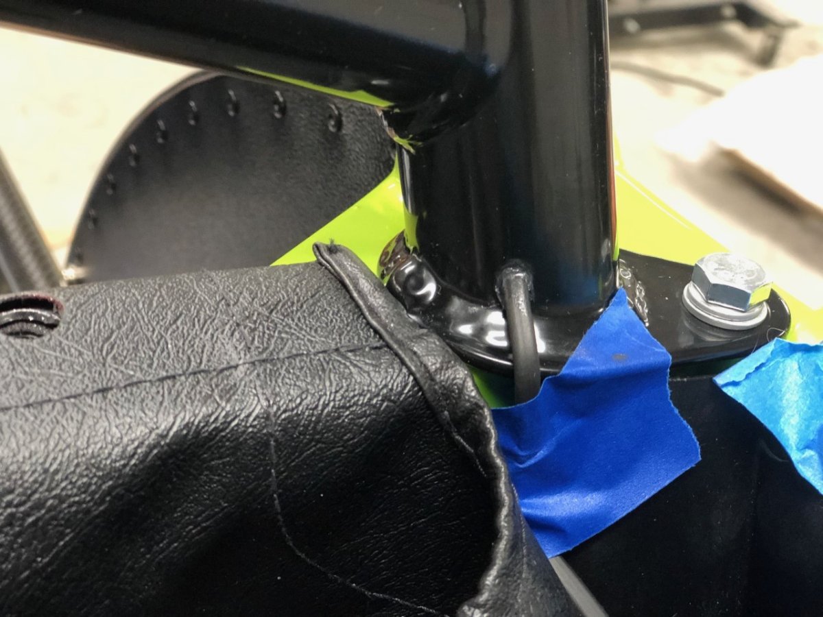
A few random updates I'll break into two posts. First, the 3rd-brake light is installed. I purchased an unused Beachman Racing setup from someone on the forum. The mount is beautifully machined from aluminum and is normally installed in its natural state, but having that as the only piece of brightwork on the car seemed a bit out of place. A light sanding, then shooting it with primer followed by Rustoleum Satin Black which is a decent match for the powder coating used by Caterham, and it blends in with the rollbar. Running the wire through the rollbar was not as daunting as it sounds. I ran safety wire, which is thin yet stiff, from the exit hole on the bottom of the rollbar up to the entry hole on the top, grabbed it with a pick, pulled it to the hole, then reached in with forceps to grab the wire and pull it out. Wires from the light were then twisted to the safety wire and sealed together with adhesive lined heatshrink to avoid separation in the middle of the rollbar, and finally the whole affair was pulled through the rollbar. Drill holes were painted to prevent corrosion and the holes were sealed with liquid gasket to prevent water ingress. Worked great. When buttoning up the rear suspension, I discovered an interesting problem with the axle nuts. These are handed with left-hand threads on the driver's side and normal, right-hand threads on the passenger side. The bottom of both nuts were 41mm, but the top of each was larger and required a 42mm socket to engage the full height of the nut. The delta between top and bottom was larger on the driver's-side nut and this difference was visible to the naked eye. Not a problem per se, but I don’t' recall seeing this in the past with any nuts. Once a 42mm socket arrived, they went on without issue. The photo below shows the driver's side nut dropped into a 41mm socket, with the greater than 41mm portion sitting above the surface. -John
-
This morning I heard back from SBD about using a fuel pump with pressure regulator rather than adjusting pressure via PWM control of the pump. I don't have the specifics yet but will share them once I get to this part of the project. Good news is that it sounds simple: "you will just have to move one of the pins in the ECU wiring hood, which is a very simple process on a MBE9A4 ECU, because the pin that controls that the digital pump controller is different to the one you would need to control a relay that can energise the standard pump. You will also need to fit just a standard 30amp relay." -John
-
Dan, if it's any help, my build is far less complex, yet I feel the same way. Although you forgot the part about the anxiety you have before making a cut or drilling a hole in an expensive, long lead time part and opting to measure 5-10 times just to be certain it's right, then stepping away for a day or two before measuring another 5-10 times and then maybe making the cut or maybe letting it sit for another day while you continue to contemplate if you overlooked anything You are to be commended for both your approach and your dedication despite all the challenges thrown your way. This one has not been easy. I'm looking forward to reading about your first drive! -John
-
@Bruce K I'll shoot you a PM for next steps on debugging this. Now back to people posting about their other cars -John
-
I've seen your post show up four times in succession, followed by a near three-hour gap, then repeating three more times. Croc's post has only showed once for me. Although I've been deleting your duplicates, you might want to examine if you were doing anything differently when submitting them. Different device, browser, stuttering, shots of tequila, etc. -John
-
No need to remove the lock. Usually just rotating the wheel so things line up is enough, but you may need to turn the key while doing it to release the lock if you've triggered it. Hopefully that's the issue. -John
-
Sounds like you are hitting the anti-theft steering lock mechanism. Have you tried rotating the wheel while gently pulling once you hit the stop? -John
-
That caught my eye too and I had the same reaction. Shoot me a PM if you need any measurements. -John
-
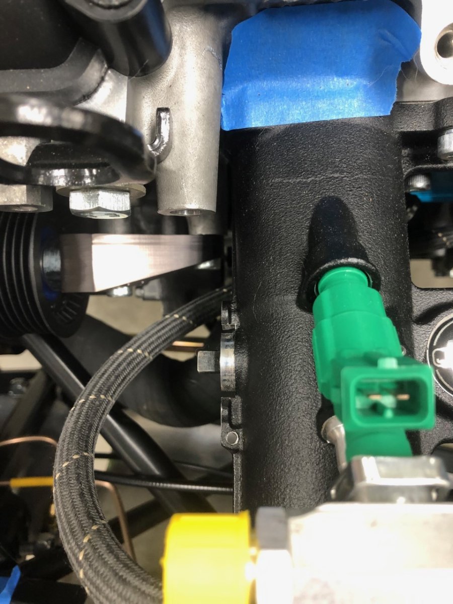
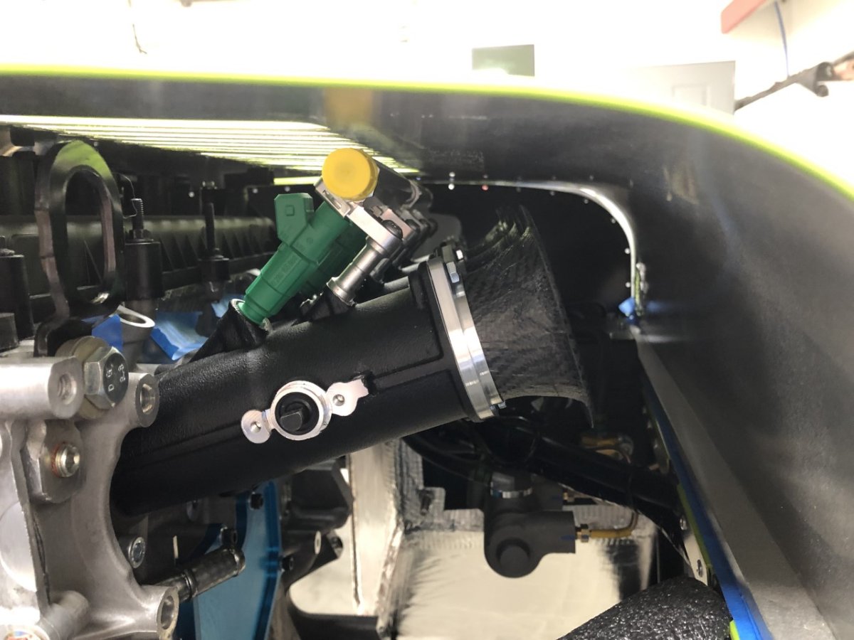
The part number used on the 420 engine is 3M5Q-6A228-AE. Here are a few more photos to help you visualize the interference with the current Jenveys which might help answer your question about your SBD TBs. Front view of tensioner. Similar to yours but there is no forward-facing bolt. Top view of the tensioner. Note where the top mounting bolt is in relation to the 420 intake runners This picture shows that same bolt boss in relation to the edge of the Jenveys and the throttle shaft. -John
-
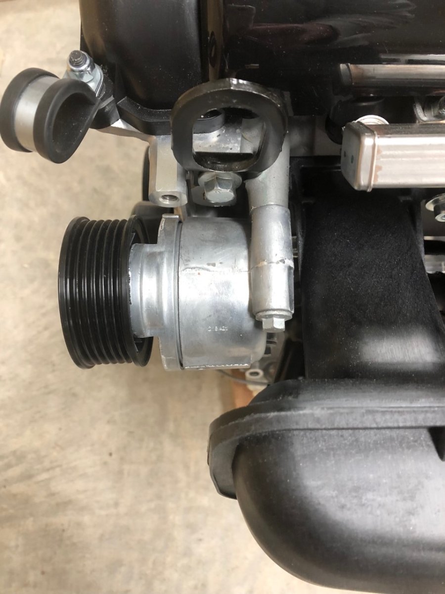
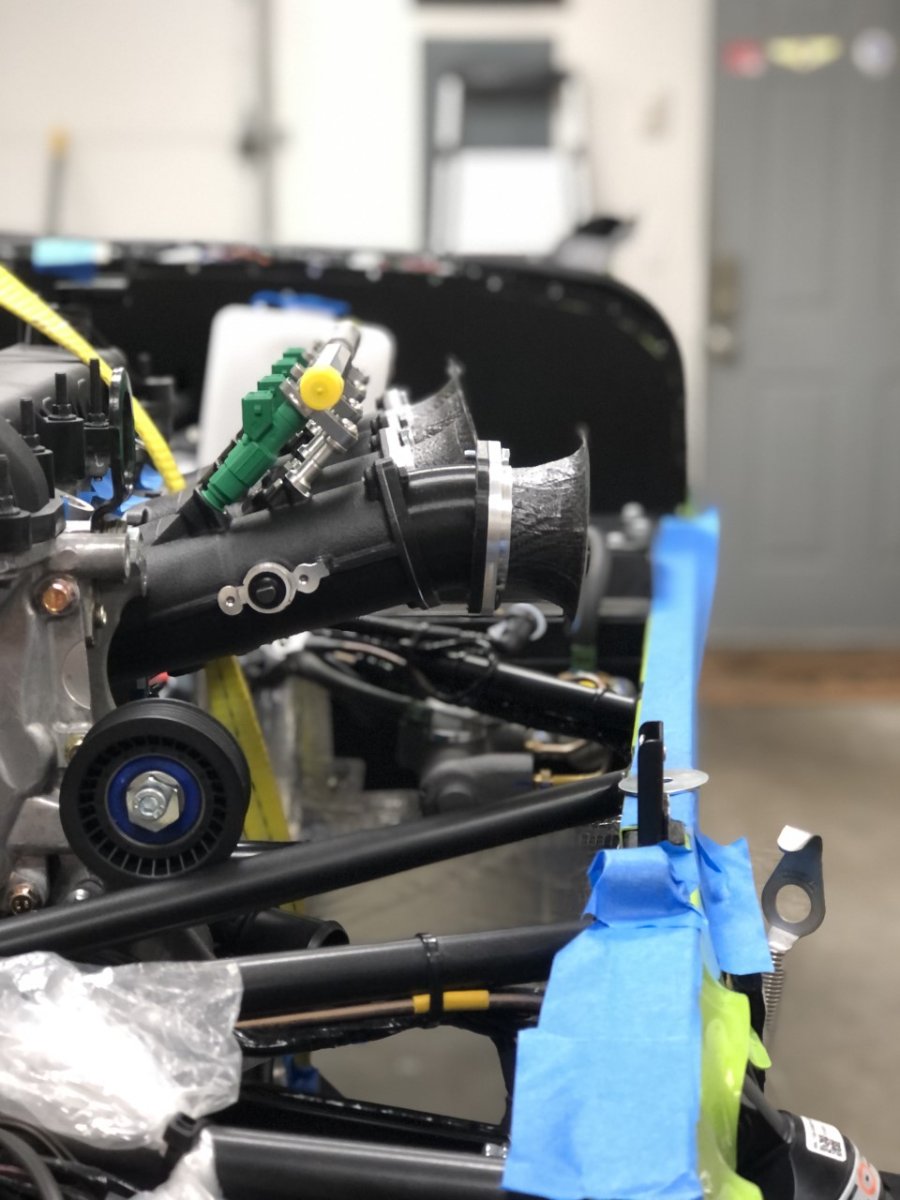
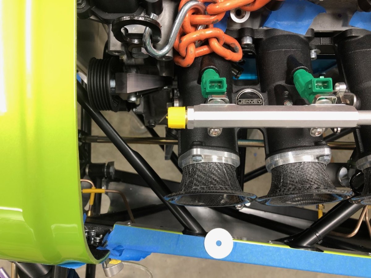
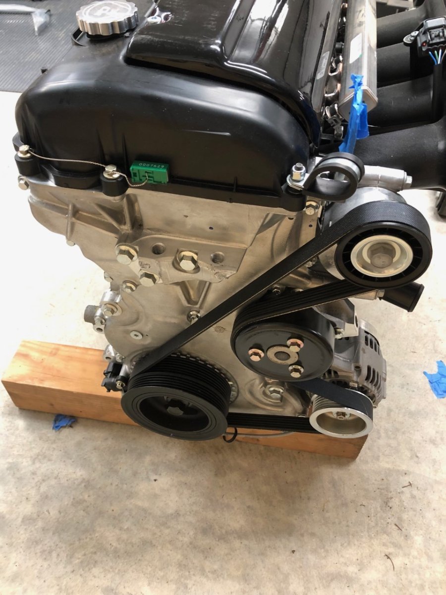
I've run the Raceline tensioner on my 2.0L Duratecs since '04. Picture below shows that setup on the most recent engine. Although the belt gets very close to itself, it has never been an issue. For the Caterham with the 2.4L I had planned to do the same but discovered that clearance between the pulley and one of the chassis tubes is really, really tight. They didn't touch but until the engine was in its final position with the trans on and mounted to the chassis, it didnt inspire a lot of confidence. I don't have a great picture to show the gap, but these two will give you an idea. The fix, if needed, is very simple: just a flat metal plate that bolts to the stock block locations and is drilled to mount the tensioner ~3/4" higher. I considered using the Ford self-tensioner as fitted to stock Caterhams but discovered it won't fit with Jenveys. It's a large, bulky part and attempts to occupy the same space as the left-side throttle shaft. The first photo shows it in place on the 420 engine. If you look closely, you can see it uses the two top mounting bosses, whereas the Raceline only uses the lower bosses. Couple of other points. First, the 2.3L block is 13mm taller than the 2.0L. I suspect that when the tensioner wheel is lowered by that amount relative to the chassis, the clearance reduces further so although it isn't a consideration for you, I/m mentioning it for anyone else reading this who has a 2.0L. Second, Raceline uses a different bellhousing than Caterham which shifts the engine back in the chassis about 20mm. This renders the potential interference with their tensioner moot as it would now sit well back of that chassis tube. -John
-
The end of this build manual from 2015 has a wiring diagram that might be helpful. If the factory eventually provides you with something, please let us know as this is a pain point for a lot of us. If you post the issues you are having, someone here might be able to point you in the right direction for troubleshooting. -John
-
Hi folks, this is an interesting conversation about auctions and worthy of a dedicated thread if there is interest, but this is a for sale ad, and we are well off topic. Out of respect for @peregrinemotors, let's please keep all further posts in this thread on topic. Thanks, John
-
I live in a world of SUVs driven by smart phone using, latte swilling, multi-taskers who consider themselves exemplary drivers. I want to mount that third brake light as high as possible. For the Caterham I'm using this setup from Beachman Racing: http://www.beachmanracing.com/rollbar-mounted-light. It requires 4 holes drilled in the bar; 2 for the mounting screws and 2 for the wiring. This is similar to the setup I have on the Westfield. I'm not concerned about impact to structural integrity. The holes are small. If I'm in an accident involving sufficient damage that someone would even raise that question in the post-accident investigation, I figure I'd be dead whether the holes were there or not. Threading the wire through the bar in the Westfield was a challenge, but it was doable. I suspect the Caterham will be similar. I'll post the process once I get to that point. -John