JohnCh
-
Posts
3,406 -
Joined
-
Last visited
Content Type
Profiles
Forums
Store
Articles
Gallery
Events
Library
Everything posted by JohnCh
-
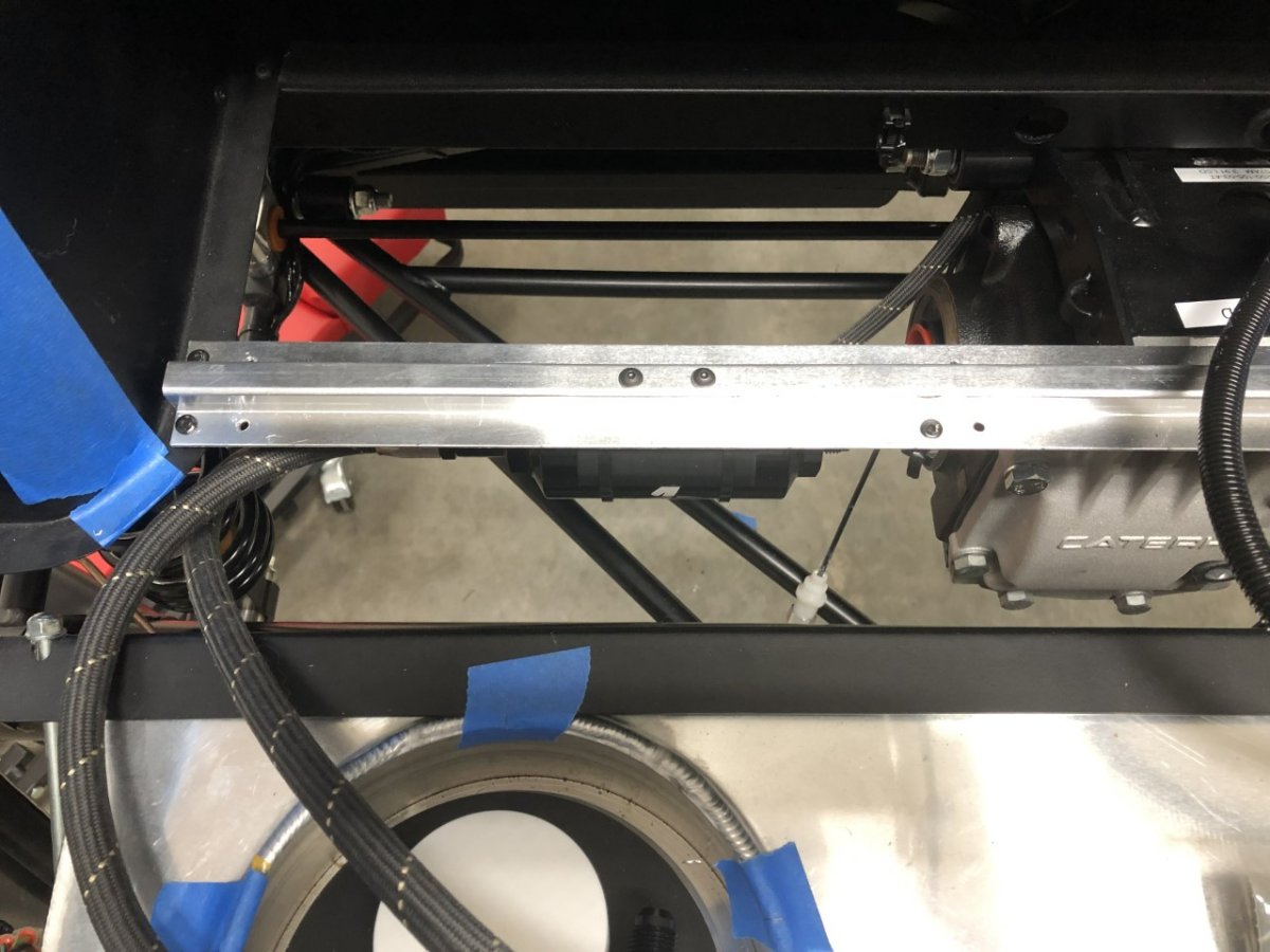
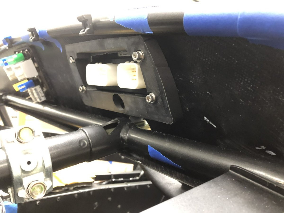
Anyone who has removed the honeycomb boot floor can attest that it's an exercise in frustration. It's one of those there-is-absolutely-no-way-in-hell-that-can-wiggle-out-without-bending-something moments until suddenly….it's out. Looking at the supporting frame, there is no apparent reason why Caterham doesn’t simply cut the floor into two pieces so it's easy to remove and install when you need to access the fuel tank. Since they didn’t bother to do it, I did. This was my first experience cutting honeycomb. It turns out that when using a thin jigsaw blade, the blade can twist within the honeycomb, creating a bevel cut and pulling the saw into the guide while slowly pushing it over despite the use of clamps. Unfortunately, I didn't catch this early and ended up with a cut that is anything but straight. Not a big deal given it's only a cosmetic issue and isn't visible when the boot carpet is in place. The honeycomb floor is now quick and painless to remove and there is no impact to the rigidity of the floor. This photo shows the right side of the rear frame for the boot floor. The red line on the tape shows where the two sides will meet once it's cut in two. The next two photos show the boot floor after the cut. First, with just the right side in place, then with both sides. With boot floor cut and fuel plumbing work done in the back, it was time to install the rollover bar. Taking a tip from a build blog, before blocking access with the bar, I ran a harness bolt into each harness fitting to make sure they weren't gummed up by paint. They were fine, but it was clear the person who drilled the aluminum strip in the back of the boot cover that sits over those holes was having a bad day. The holes for the passenger harness bolts were partially blocking the threads, and it appears they tried drilling those holes a few times, because they were not a shape one would confuse with round. Removing it from the car then cleaning things up with a file and it was time to install the rollover bar. As others have found, bolt alignment was off. In my case, a pair of ratchet straps were required to move things around enough to get all six bolts in place. Tomorrow I'll drill the holes for the 3rd brake light and prep and paint the aluminum mount. -John

-
The kit includes all the parts necessary to build a running car. Lead time is a combination of demand outstripping supply which results in a waiting list, supply chain issues, and my opting to wait another few weeks to ship with two other cars and save several thousand dollars in shipping costs. If you want to learn more about the Caterham assembly process, from what the build entails to all the included parts down to the fasteners, check out the latest build manual and the detailed build blog linked to below. Caterham Assembly Guide v2.3 Caterham Detailed Build Blog -John
-
Thanks, I made the one in the Westfield and it turned out well, but I would prefer the part to be powder coated or anodized rather than painted and doing so for a single part is expensive. If I can't find a US source for the 2" PCD spacers, then I'll just buy it from the UK and bundle it with some other items that are difficult to source here or significantly cheaper over there.
-
Ah, I misread that and thought the comment about making it heavier was referring to the stock knob not a new one you have already fabricated. But yeah, experiment -John
-
Personally, I'd experiment to determine which I prefer. Even if 9 out of 10 people here state they prefer the stock weight, if you prefer heavier, then that's the right answer for you. Perhaps tape different amounts of lead weight to the stock knob and try it out? -John
-
Yes, I'm aware, thanks.
-
The Caterham prices are on the high side. Those same switches (Apem) are available for less from other sources such as Car Builder Solutions in the UK or through various electrical supply houses in the US. The stock exhaust will hold things back. In theory it will cap the fun in the 250-260hp range, which is fine for now. Phase 2 of the build -- if needed -- will be a custom exhaust and appropriately sized Raceco silencer which should increase power potential to the 270-280hp range.
-
Sorry, I should have mentioned this is for the 3-hole style.
-
I'm trying to locate a 1" spacer for my steering wheel, but the only ones I can find in the US are drilled for a 1.75" PCD whereas the Momo uses a 2" (50.8mm) PCD. That larger size is readily available from multiple sources in the UK, but before I commit to international shipping, I want to rule out a US source. Any leads? Thanks, John
-
I'm not too proud to admit having a little exhaust envy upon seeing the car. -John
-
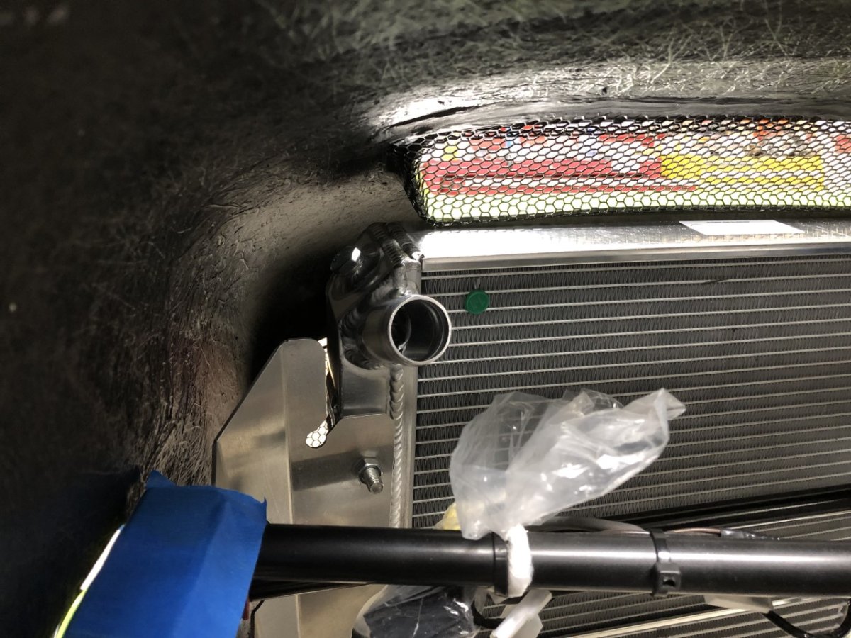
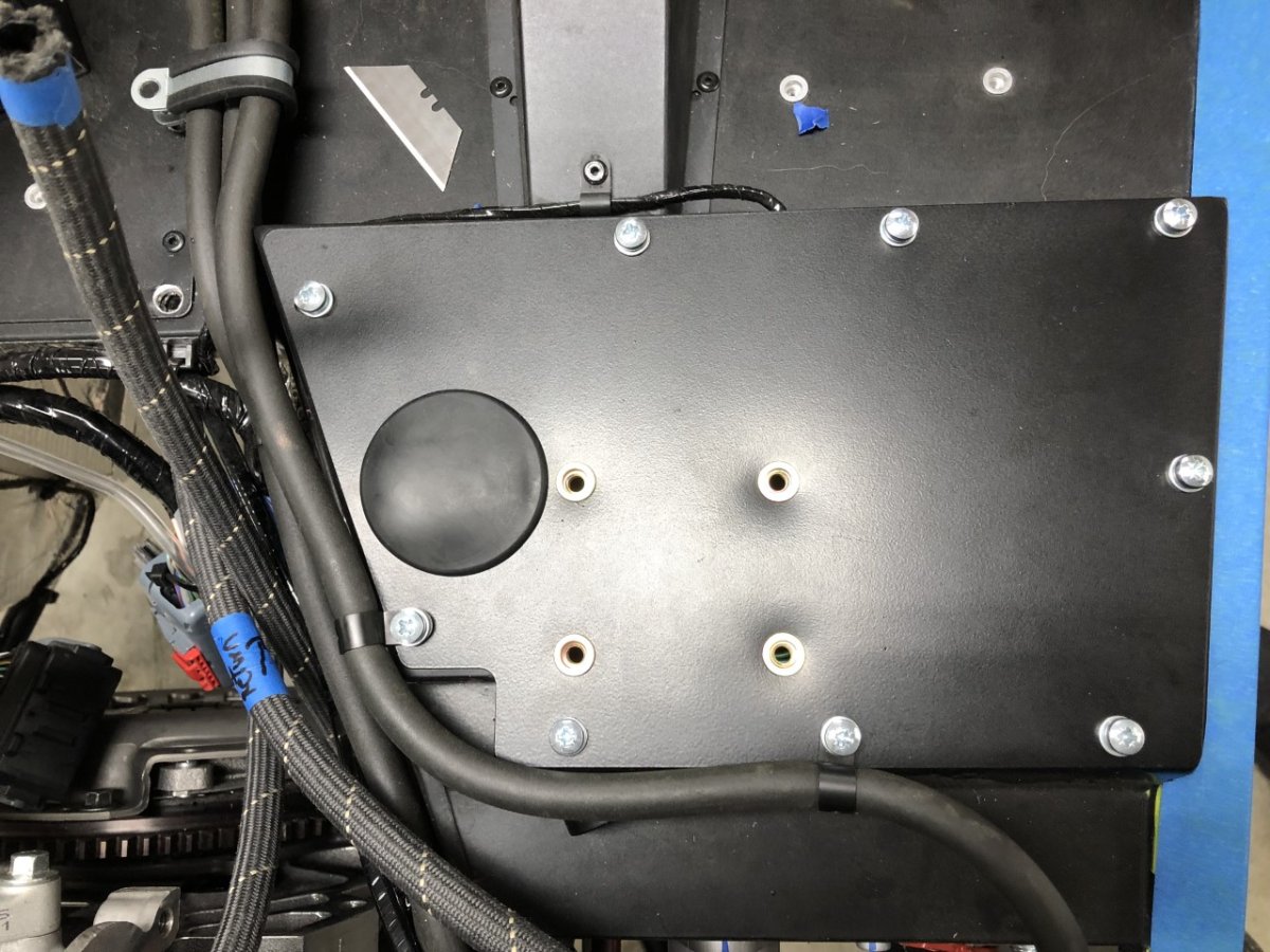
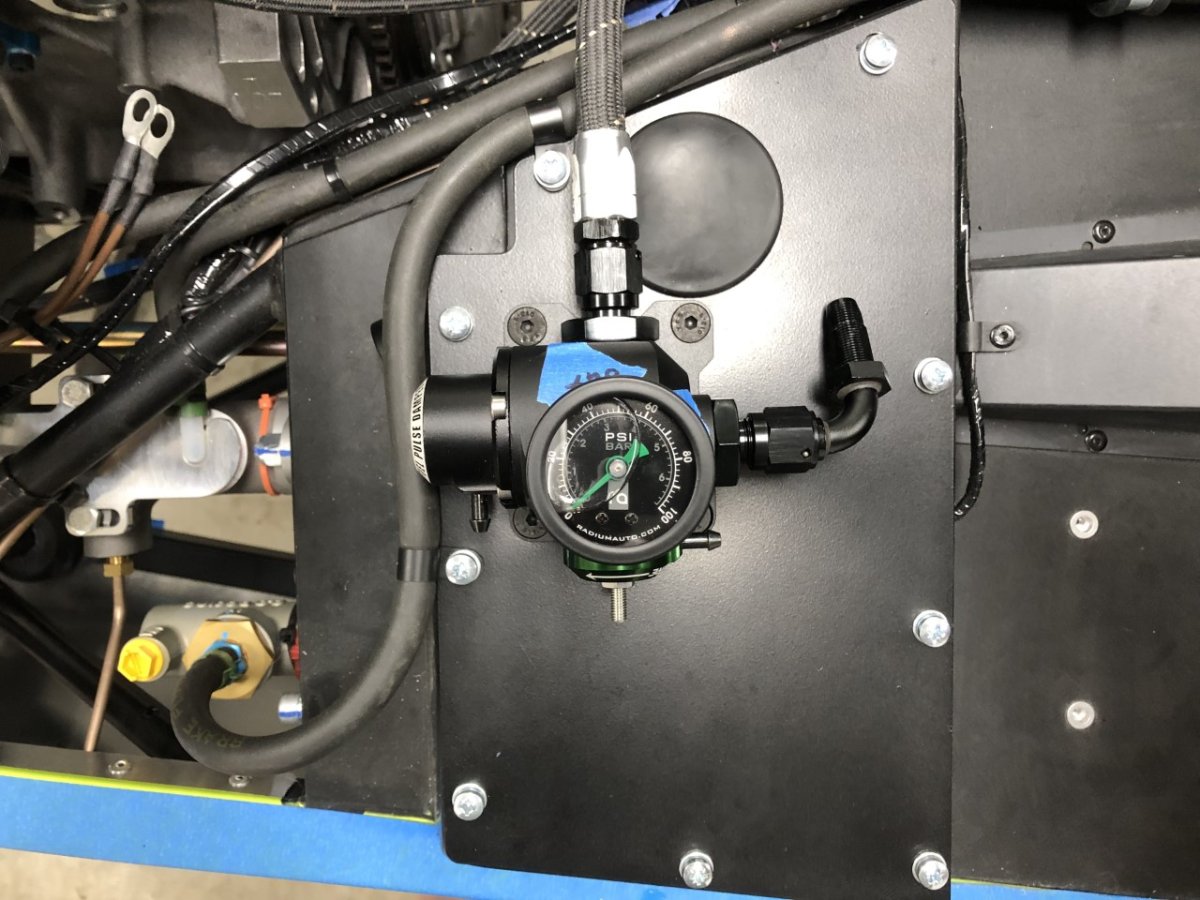
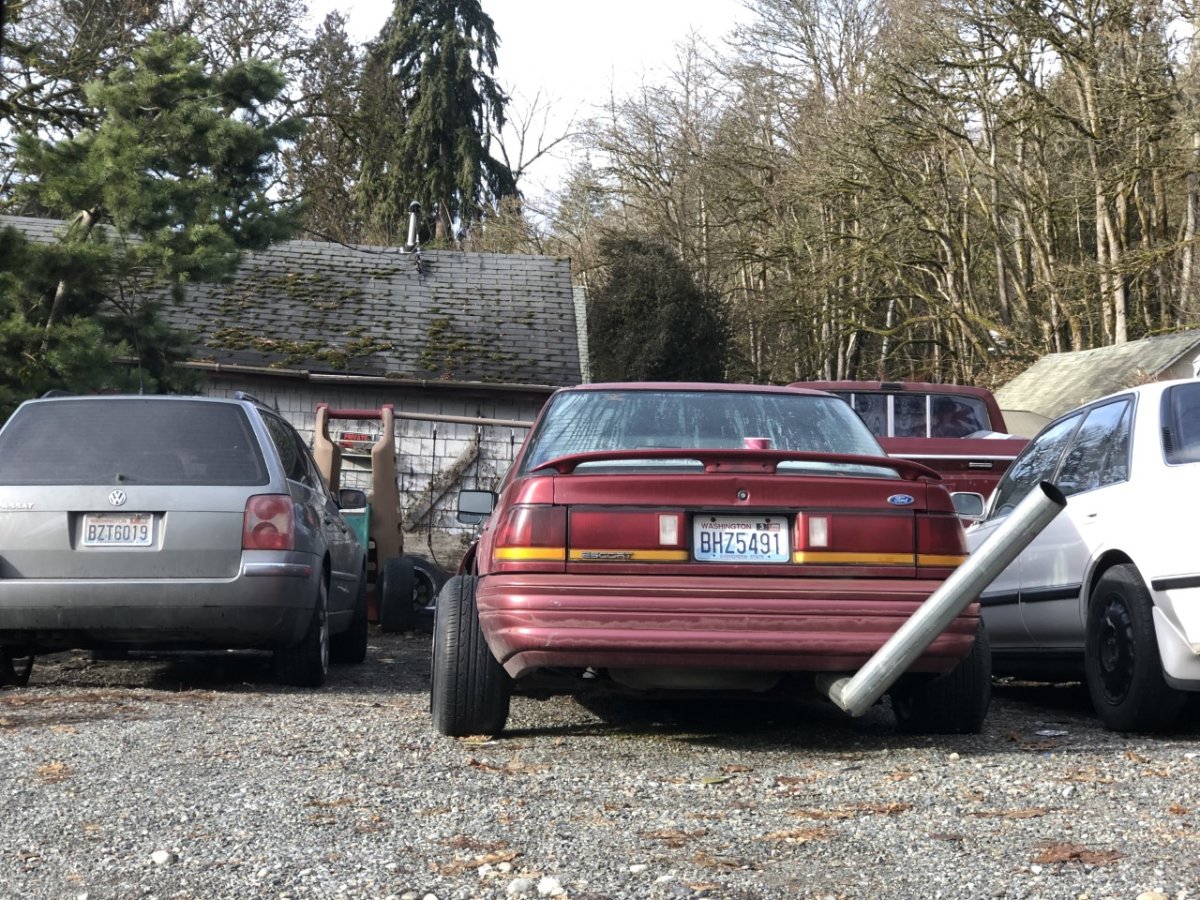
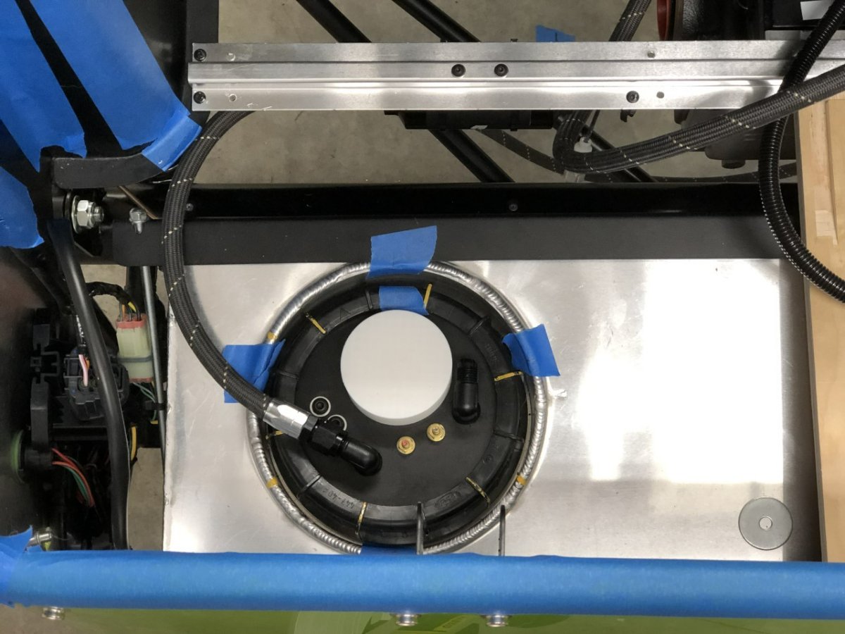
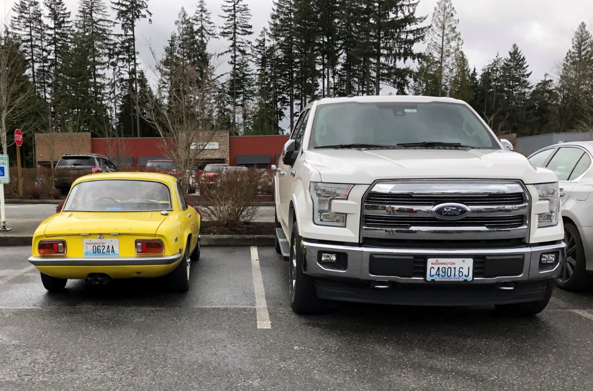
A few quick updates. After confirming with Bruce Beachman that something was amiss with the radiator brackets and not the chassis tabs to which they attach, I clamped the brackets to the bench and tightened the angle to 90 degrees. Before doing so, I checked the angle of the two bends that should combine to form the 90-degree angle to see if one of those was out. It appears they were both off by about 3 degrees which together made the big difference. At least the person who makes these was consistent with his errors With that locating the radiator correctly, there is still some minor interference between the bottom corners of the grill covering the 620 intercooler scoop and the top of the radiator. Given the grill is metal, this seems like a potential wear point for the aluminum radiator. Before attempting to lower the radiator a few mm or file down the grill, I might just put a piece of foam rubber between the two and monitor it for wear. If it's not an issue, then leave it. If the interference is destroying the foam rubber, then correct it. A couple of missing fittings arrived which allowed completion of the in-tank pump assembly sans fuel sender followed by a test fit with the Hydramat in the tank. Everything seems to fit just fine. Rivnuts were used to mount the FPR/Damper to the pedal box access panel. The return hose is fitted, but I'm waiting on plumbing the line from the fuel rail until another 90-degree fitting arrives. This photo is somewhat build-related since I came across this car while running an errand to pick up a part. Umm….. -John
-
Follow the link below to the help guide on sending a PM. if you are having trouble after following those steps, feel free to contact me for assistance using the Contact Us link located at the bottom of any page. -John
-

Driving with no center console: reduced buffeting?
JohnCh replied to TurboWood's topic in General Tech
I've never heard of those. I'll need to research them. If they work, it shouldn't be too hard to print up something that would mount to the windscreen frame. Thanks, John -
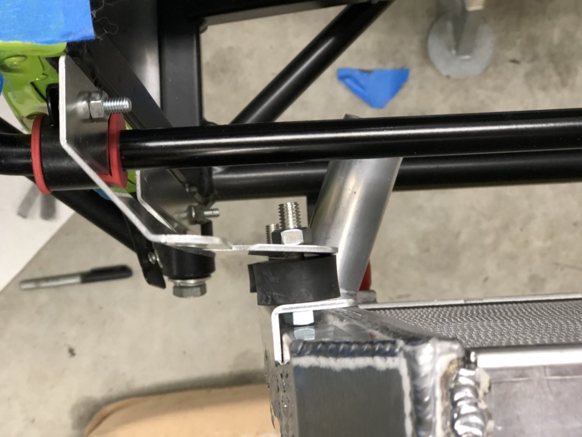
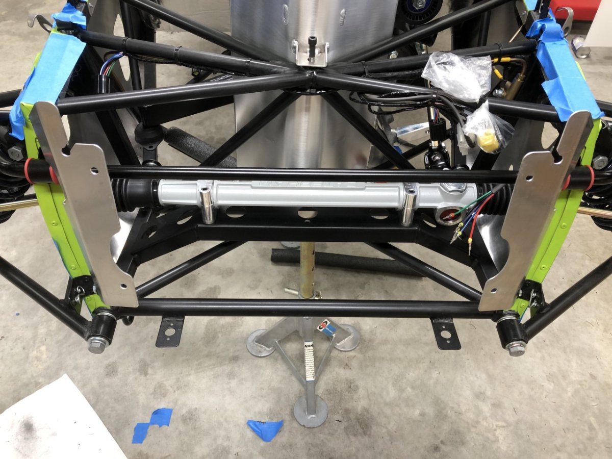
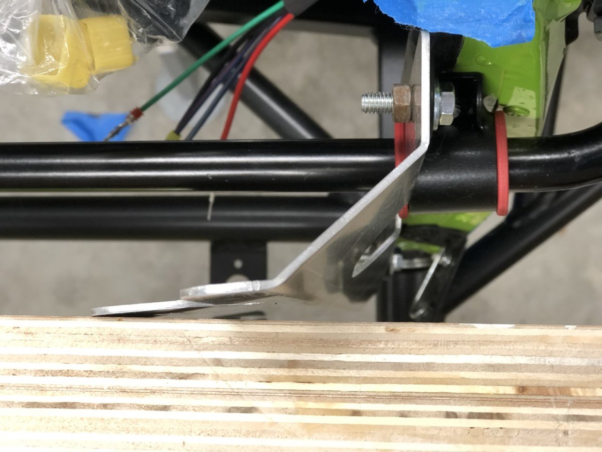
I worked a little more this morning on clearancing the nosecone cutouts for the front lower wishbone bolt heads, then attempted a temporary radiator install so I can begin working on cold air intake packaging. To my surprise, the radiator brackets are not bent so the two mounting planes are 90 degrees apart (photo 2). This seems like it will put some additional stress on the radiator when the bobbins are torqued (photo 3). Is this normal or should the front of the brackets be parallel to the radiator? Thanks, John
-
Thanks, that mostly makes sense to me, but I'm getting hung up on this comment: Tracing wires, it appears the YG wire is controlled by the fuel pump relay which is triggered based on a switched feed. Assuming that's still the case with your rewire, then it seems a rare occurrence when the key is turned but the engine is not running for more than a few seconds unless there is a problem: i.e. the safety issue you mention. I just want to make sure I'm not missing something. @Croc I hadn't thought about a clear coat and professional refinish. Definitely something to consider. Can any Seattle-area members recommend a place on the Eastside for this? As for finger clearance, the wheel position in that photo has tons of clearance, however, it does reflect the positioning based on the 1" spacer I plan to add between wheel and hub. Thanks, John
-
Driving with no center console: reduced buffeting?
JohnCh replied to TurboWood's topic in General Tech
This is something I've been kicking around and plan to do some experimentation when the car is done. I remember reading somewhere many years ago that drilling a large hole (2-3") in the lower center portion of the windscreen dramatically reduces buffeting. From my own experience, very large wind deflectors make a huge difference, but at the expense of even more drag. Given what they can do in racing with aerodynamics by redirecting and speeding up/slowing down air to create high- and low-pressure zones in very specific spots, I suspect there is an opportunity for air management to make things more acceptable. i.e. use walls of air to change what's occurring rather than redirection by big pieces of Lexan. At some point, I'd love to tape strings of yarn all over the car, then attach a 360 deg camera to the roll bar and get a good look at what's happening. -John -
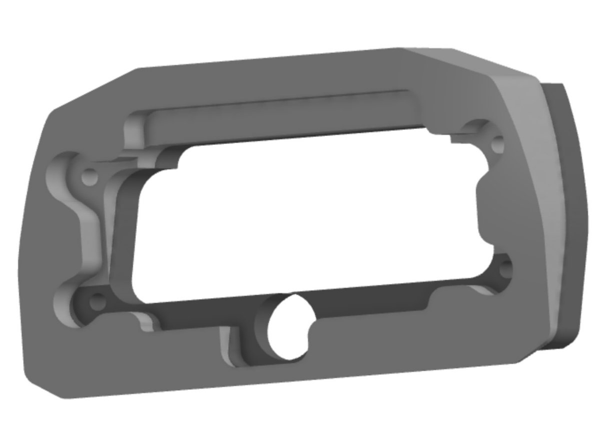
@sf4018, are you saying that without the pump control relay, the pump is fed by a constant 12v+ feed and runs even with the key off? I've had a change of plans and will no longer use the Emerald ECU and will instead use an unlocked MBE so this is something I'll need to address. I was under the impression from the factory that the stock pump can be run full time, so perhaps this is simply a setting in the software if the relay is not removed? Speaking of the ECU, as I dug into figuring out how to splice in the loom given it duplicates parts of the chassis harness (e.g. main and fuel relays), I realized this was a much bigger project with a high probability of creating head scratching problems down the road. None of the available wiring diagrams match my car and they are not particularly user-friendly for tracing by an amateur; or at least not compared to what I'm used to using. It seems there is a high probability of unintentionally orphaning a circuit and there will either need to be sufficient carnage to the chassis harness to make reverting to stock a nightmare, or I'll have tons of wires and two big connectors sitting in the engine bay if I try to keep it whole. Bottom line, it will look amateurish, which is not the look I'm going for. Just because I don't know what I'm doing, doesn't mean the car has to broadcast that fact whenever the bonnet is removed. In the interest of my time and what's left of my sanity, I've decided to leave the Emerald for a future upgrade, at which point I'll probably pull the harness and redo something with PDM control. This does mean I lose traction control, knock control, and switchable maps for now, but it also means finishing the rear suspension is no longer on hold due to the reluctor ring delays, and I won't need to deal with working out the sensor brackets and wire routing to the 4 corners. Given my speed, that's 4-6 weeks' time savings right there Thanks, I'm pleased with it. One surprise is how well the carbon fiber nylon filament complements the carbon dash. There is a grayish sheen to it that is a match for the grayish, shiny portion of the carbon fiber weave. It actually looks intentional from a design standpoint. Below is a screenshot from CAD that shows the parts. The AiM slips into the front of the lighter gray portion, and the darker gray is the back piece which is a little shorter to fit between the dash hoops. The carbon fiber dash is then sandwiched between the two. I know you do 3D printing. if you are interested in the source files, just let me know. -John
-
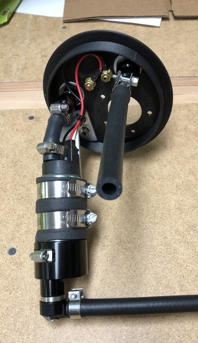
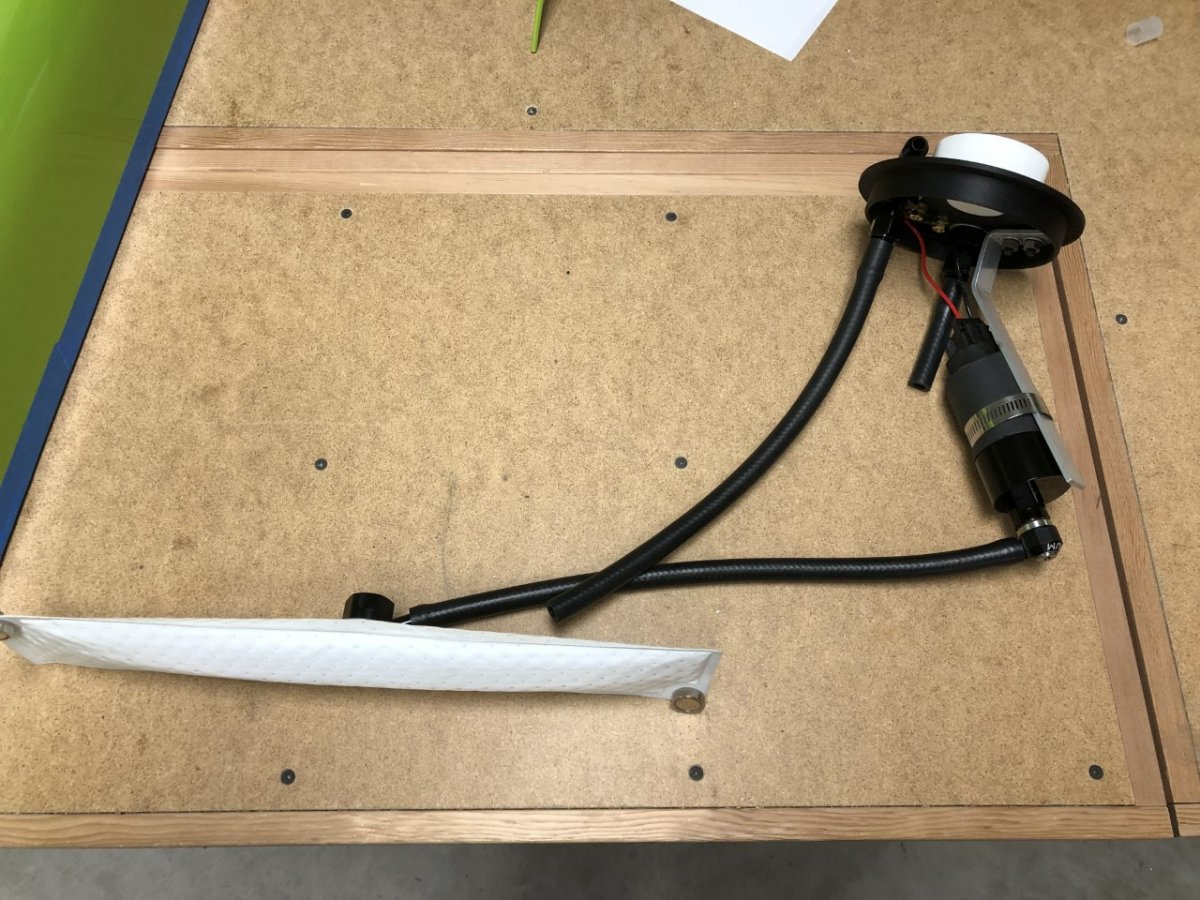
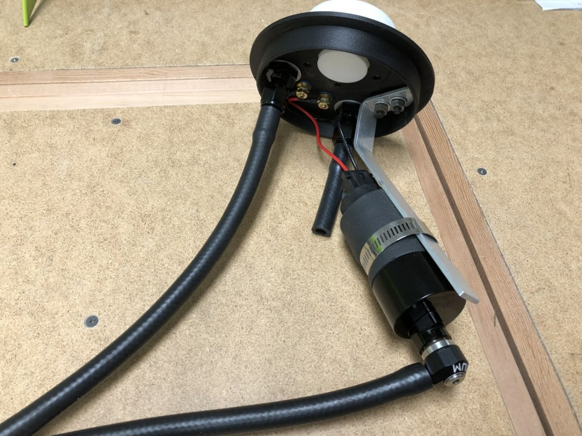
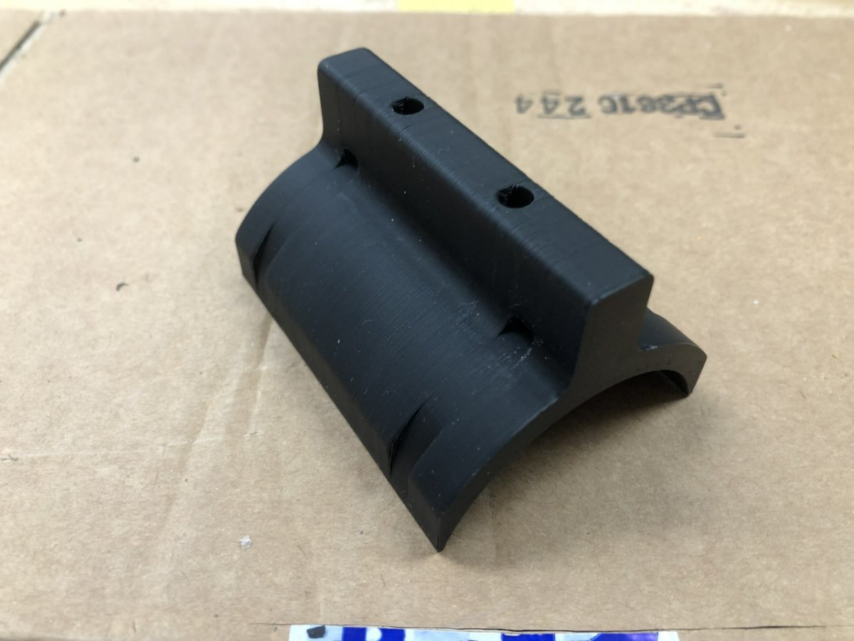
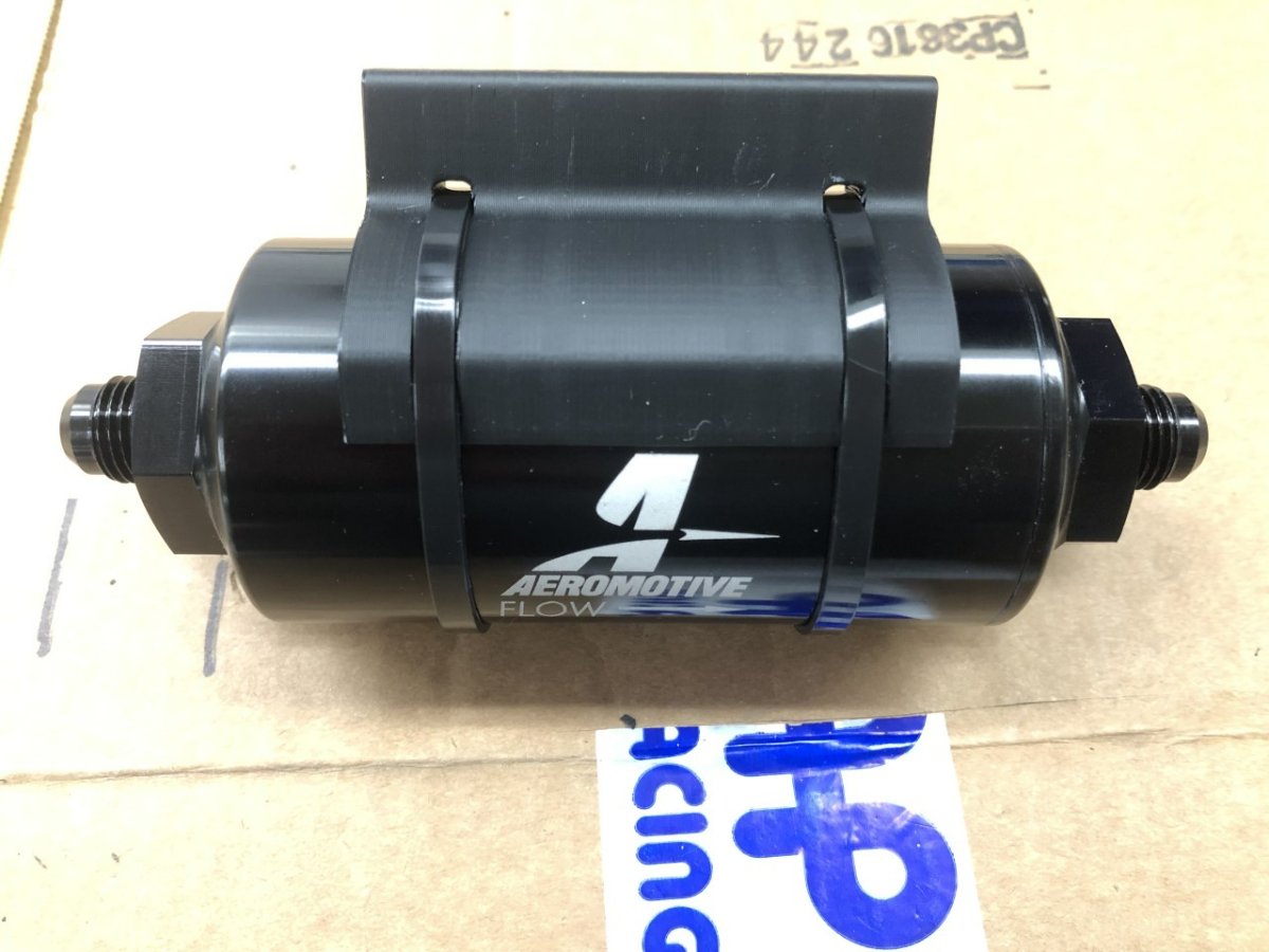
Next up, the fuel system. This isn't quite finished. I'm still waiting on a couple of fittings, but it's close enough to show pictures of in-progress work. The biggest challenge was fabricating a replacement fuel pump/sender/pre-pump filter assembly. As noted earlier in this thread, the stock setup doesn't allow the pump to reach the last gallon of fuel, uses a pump that is reportedly marginal for the power levels of this engine, has a sender that is more directional than accurate, and uses very small diameter hose. The replacement is a 3D printed lid, 255 lph pump, AN -6 fittings, capacitance fuel sender, and a Holley Hydramat. The fuel sender isn't here yet, but the white cylinder in the photo represents the head unit. A 1/2" diameter tube then extends into the tank at an angle, ending about 1/2" from the bottom front. Space in the tank is really tight and it took some fiddling to make all of this fit. Much time was spent experimenting with different fittings and how things were located on the lid to optimize available space. Unfortunately, I had to do this twice as my first attempt was made before fitting the Hydramat in the tank. When I did so, I discovered the tank has a baffle in the middle which forces the Hydramat closer to the fuel pump assembly than I anticipated. With the specific space constraints, this meant moving the pump from the right side of the lid to the left, then working out where the submersible hose and fuel sender tube would cross. Once the 90-degree fitting that attaches the Hydramat to the intake hose arrives, the fuel pump position on the aluminum bar can be finalized. I'll add a second hose clamp, cut the excess bar, and file some reliefs to help position the hose clamps. Then cut the hoses to length, add lock nuts and finish it up. I just hope it works One of the other shortcomings of the factory setup is a lack of a post pump filter. The sock that pulls the fuel to the pump operates as a pre-filter, but there is nothing between the pump and the injectors. To address this, I printed up a fuel filter holder that mounts the filter under the boot floor. It's out of the way but easy to access for maintenance. If one of the two missing fittings arrives tomorrow as planned, I should have the fuel plumbing 90% finished this weekend. That last 10% is the hose run from the front of the rail to the regulator/damper and requires that second missing fitting, which I don't expect until the end of next week. -John
-
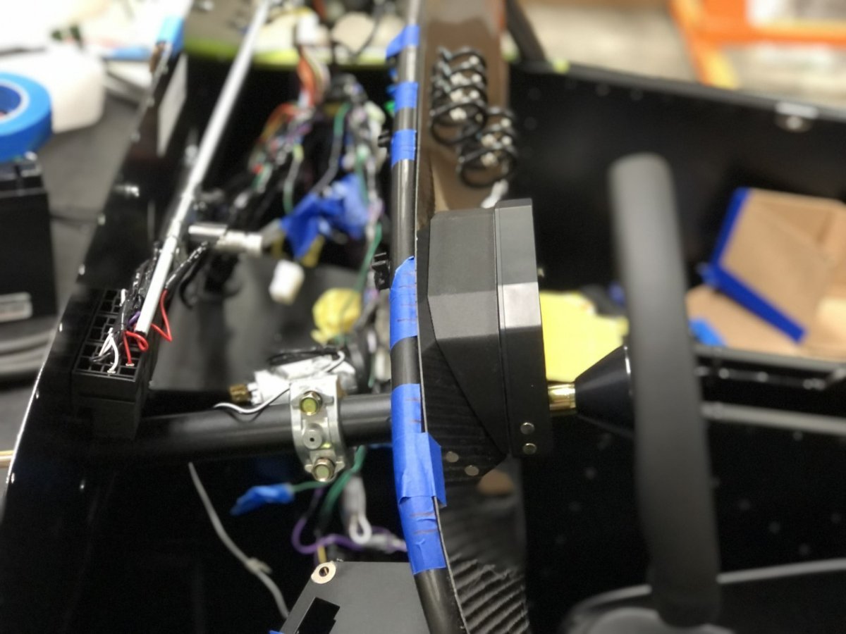
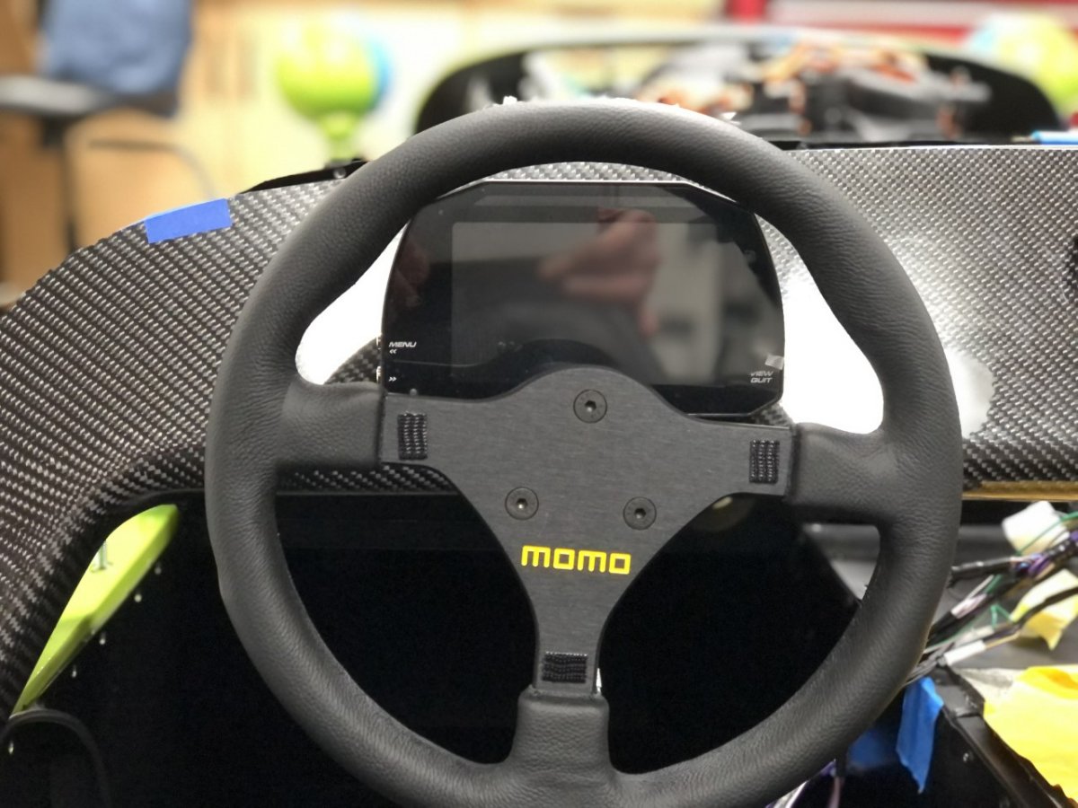
For the AiM display, rather than attach it so the screen is in the same plane as the dash where it's prone to severe glare on a sunny day, I designed a two-part bezel that tilts it forward a little over 20 degrees and doubles as a clamp to attach it to the dash. This positions the display directly at the driver rather than over their head. Because the seat and steering wheel are not orthogonal to the dash, the seat and wheel were temporarily installed and adjusted for me, then the display location was optimized so it is centered in the steering wheel when viewed from that position. This means the display looks a bit off center when viewed from anywhere other than the driver's seat. Still to come are the steering wheel mounted buttons and the hidden glove compartment which will mount in front of the gear lever. -John
-
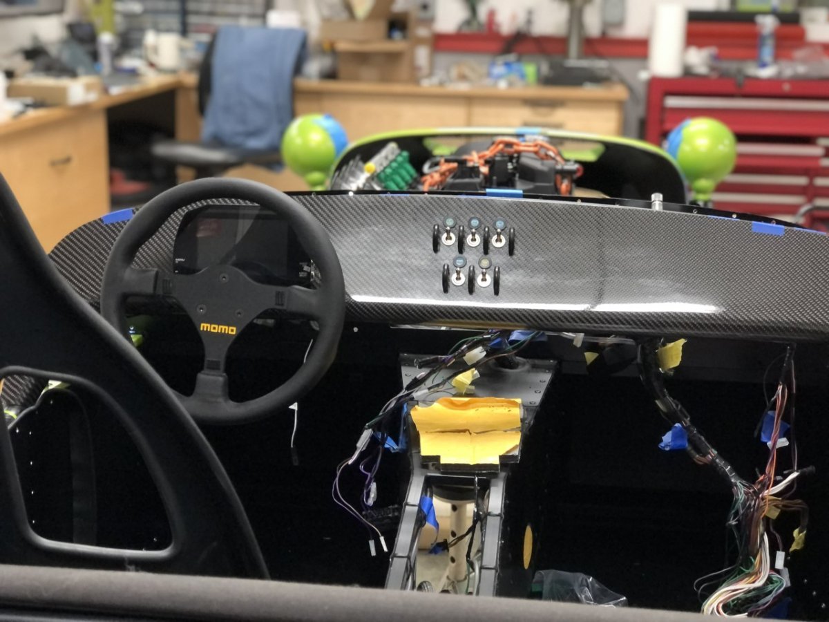
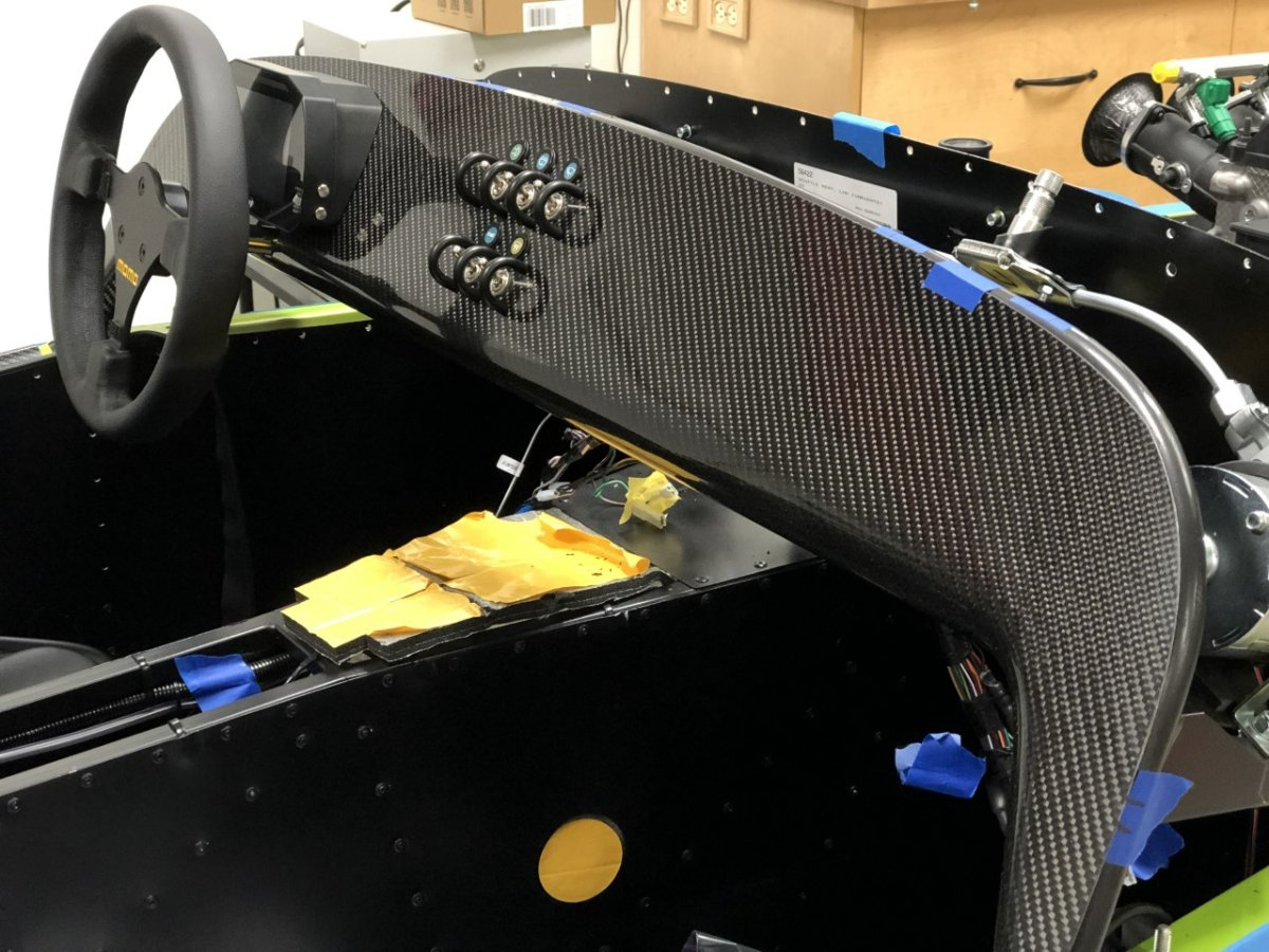
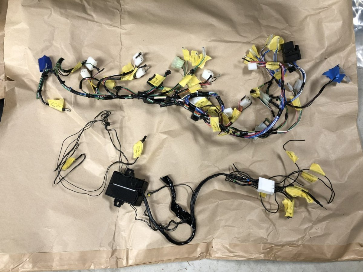
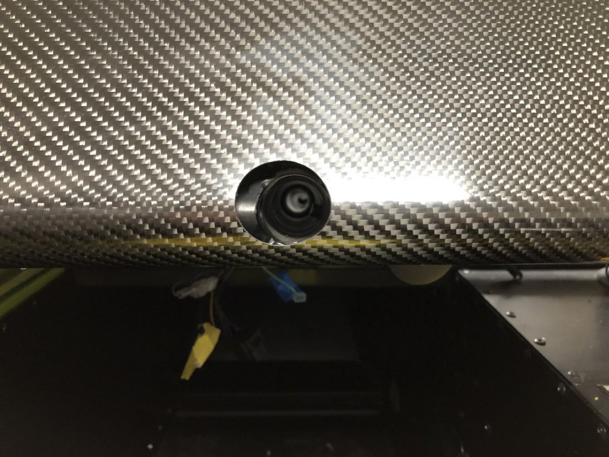
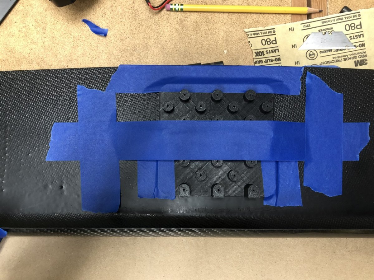
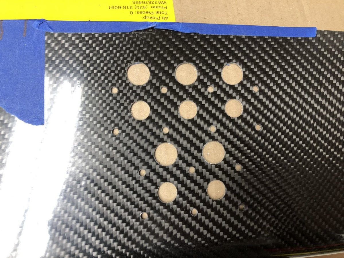
Time for a long overdue update. The past month has been marked by a lot of activity but not much in the way of results. Between shipping delays, incorrect parts, two snowstorms, one ice storm, one windstorm, power outages, and the flu, things have taken a lot longer than expected. This has been compounded by far too much head scratching on how to make everything fit. Every aspect of the Caterham is very tight compared to the Westfield. Things I assumed would be easy to fit based on the Westfield, are anything but on the Caterham. Because this update is long and picture heavy, I'll break this into a few posts. First up, the dash - part 1. Before working on the dash itself, this was a great opportunity to de-immobilize the car. With that out of the way, the 420 gauge and switch sub-loom was removed in preparation for the 620 replacement loom, which has been on order for….months. The immobilizer is the bottom loom in this photo. Although the blank dash Croc acquired from Westermann for CatKong was well made and fit without any fettling, the dash they sent me appears to have been made from a different mold. The quality is not to the level that I expected. The hole for the steering column is offset by 1/3", the shape was off and required removal of 1/8" - 3/16" of material around the shoulders of the dash so the scuttle would fit, there are few places where mold surface imperfections are visible when the light hits it just right, and the surface was scuffed. Some time with 80 grit sandpaper, a file, and a buffing wheel made things acceptable from a fit perspective, but the cosmetic issues still bother me. In some light, it looks great. In others, it looks old and a little worse for wear. To be fair, the stock dash also arrived with some scuffing, albeit, not as severe. I plan to leave it as-is for now, but prior to gluing it in place, I may remove the display and switch gear then tackle it again with a more aggressive polishing compound. If anyone has experience here, I'd love the advice. Cutting the holes for the switches was a little nerve-racking. First challenge was drilling the holes in precisely the right spots. To facilitate this, I printed a drill template sized for a 1/16" drill bit that placed the switchgear to the factory 620 spacing, and aligned everything correctly in the vertical plane when rested on the lower hoop. Second was the drilling method. The Internet experts have a lot of opinions: specialty spade bits, sharpen normal drill bits after every other hole, only used carbide bits, drill backwards, only get the size close, then finish with sandpaper, etc. Through a little trial and error on the small section of dash cut out for the AiM, I discovered that a stepped drill bit works great on carbon fiber. I used normal, unsharpened drill bits, increasing in size from 1/16" to 7/32" then switched to the stepped drill bit and prayed to multiple deities. To add a little more rigidity, a backing plate was printed out of carbon fiber impregnated nylon. This is a great material for car parts as the carbon fiber adds rigidity, and the nylon is chemically resistant, and can handle 160C temps. I'm using this material for the other 3D prints that are part of the build. -John
-
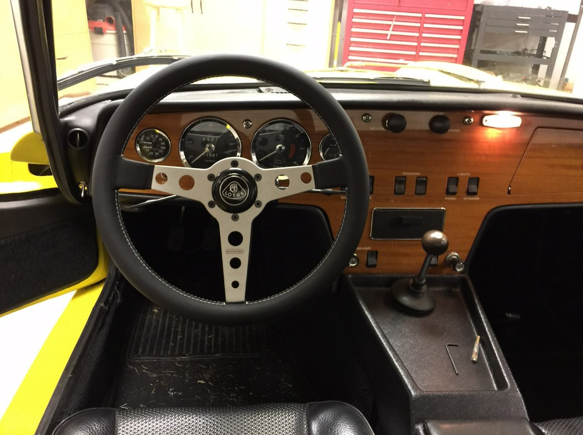
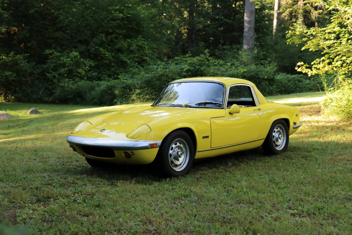
As long as we're talking about yellow Elans... I've lusted for an Elan since I was a kid and was finally able to scratch that itch 4 years ago. It's ridiculously narrow, immense fun, and shockingly competent for a car introduced nearly 60 years ago. The previous owner spent a bunch of money on a mechanical and interior refresh and various upgrades, including springs and shocks from Tony Thompson Racing in the UK, RD Enterprises header, small alternator, alloy fuel tank, Euro-style intake, bigger radiator, dual cooling fans and a few other items. I added a hollow front ARB from Kelvedon, Michelin XAS FF tires (very grippy), swapped the spare tire for a lightweight compressor and tire repair kit, gear reduction starter, a programmable 123 Ignition that had the curve set on the dyno, and spent a lot of time tweaking the rebuilt Stromberg's to improve throttle response. The car tips the scale a touch under 1500 lbs and never ceases to impress down a back road. -John
-
So, tell us a little about yourselves
JohnCh replied to slngsht's topic in General Sevens Discussion
I find a hybrid approach is best. Use a single thread to document the build and ask questions along the way. When you run into an issue that is more of a standalone problem not necessarily unique to you, and you aren't getting an answer in the thread, then it is useful to broaden the net with a new post and update your build thread with the answer or a link to that other thread. This way your build remains fully documented in a single thread, but when needed, you can get more eyeballs on the problem. That standalone thread may also be easier for others to find in the future via search if they are running into the same problem. -
So, tell us a little about yourselves
JohnCh replied to slngsht's topic in General Sevens Discussion
That sounds like a challenging project! Definitely start a thread in the Build section so we can follow along. Cheers, John -
I'm not sure what the situation was 10 years ago, but the current Michelin XAS tires are quite good. They come in both standard and FF (Formule France) versions, the latter of which Michelin refers to a competition compound and is what I run on my Elan. It's quite sticky and has exceeded all my expectations. Downsides are they require a tube and they are expensive. I've heard good things about the CN36. I'm looking forward to hearing your impressions in April. -John
-
Very cool! Did a little digging and apparently it was a Cobra-powered S3 run by Dan Morgan in 1966. @SevenAmerica, who knows all things Lotus 7, may know more. -John