JohnCh
-
Posts
3,406 -
Joined
-
Last visited
Content Type
Profiles
Forums
Store
Articles
Gallery
Events
Library
Everything posted by JohnCh
-
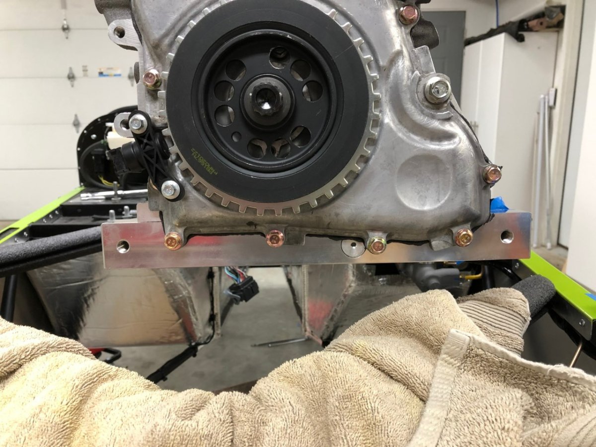
Drilling out the side skin to clean up the holes was uneventful. With that blocker out of the way, I decided to try the temp engine install again after work. Based on everything I've read, installing the engine is tight in these cars, but I assumed that since I wasn't installing the engine/gearbox unit, and simply the long block, this would be easy. Just drop it straight down. Well...no. Doing it solo was a lot fiddlier than I expected. I couldn't just drop it down, but rather had to move the block fore and aft as I slowly lowered it down while simultaneously pandering to my paranoia about damaging my new car. Once the engine was roughly in place, and the RH mount could be reinstalled (otherwise, chassis tubes are in the way), I discovered it was impossible to get both engine mounts to align. With one side aligned, the other was always slightly out. It was close, but not close enough to force the issue. Surely, I was missing something? I kept at it, willing chassis tubes and the engine to occupy the same space at the same time but was unsuccessful. Then I had an epiphany. Well, more of a hypothesis that made me swear up a storm in anticipation of being proven correct. Caterham uses the Raceline dry sump system. To keep it simple, I bought the Raceline dry sump system for this engine. Raceline and I had many conversations about my project, and I obtained a lot of parts from them. i.e. they knew this was going in a 2022 420R SV. It turns out the front of the dry sump pan they provided extends out from either side of the block by about 35mm more than their pan fitted to the Caterham 420 engine. The extensions contain through-holes that appear to be engine mounts for a different installation. With that extra material in place, engine installation is a physics impossibility. Tomorrow, I break out a hacksaw and files. Tonight, I open a Guinness. Or two. Or... -John

-
Thanks @MV8 I missed that when digging through that version of the manual, but it is the size I initially bough. Bruce Beachman also got back to me quickly, confirming the size and that I will need to drill into the side skin. -John
-
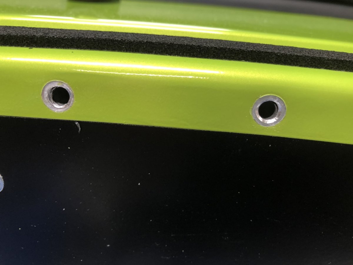
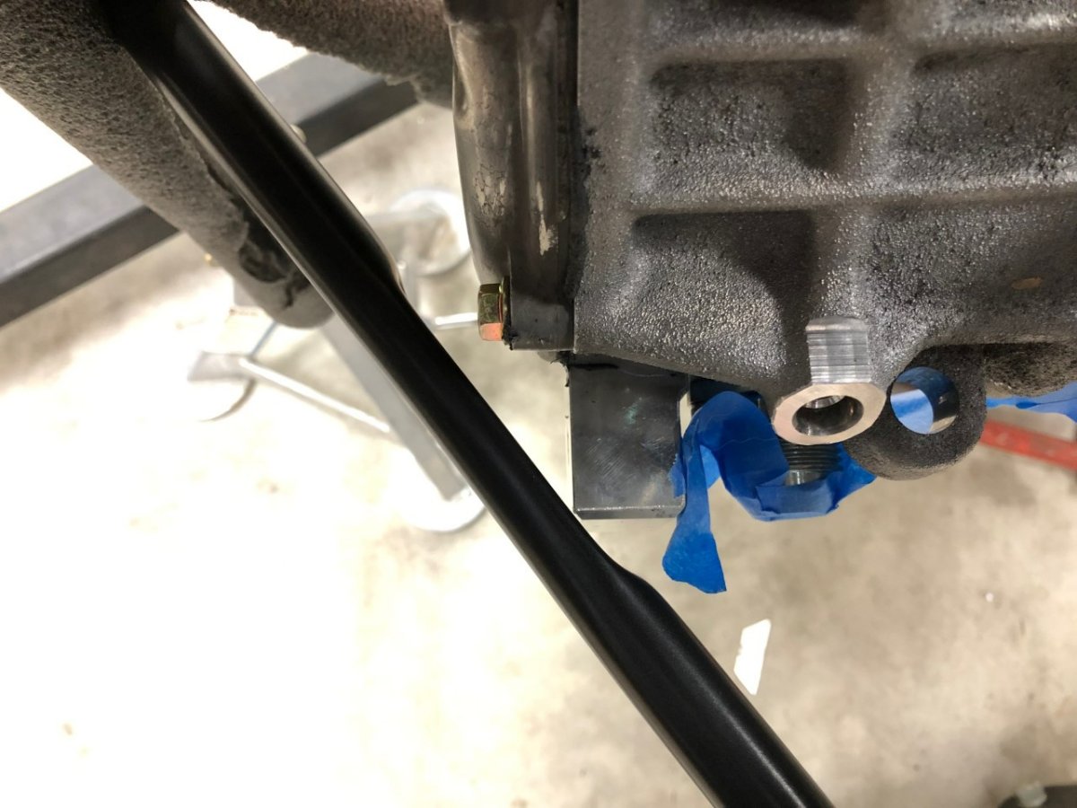
I planned to do a temp install of the engine over lunch today to help me sort out available space for my non-standard items. Of course, Caterham forgot to include the bolts that attach the engine mounting bobbins to the chassis and the size is not listed in the various build manuals I have on hand. Based on the size of the holes in those mounts and the matching holes in the chassis, it looks like either M8 or 5/16". Opting for the former, and buying suitably sized fasteners, I discovered that when Caterham punched the hole in the bottom of the side skin for those fasteners, they drove up some of the aluminum skin several mm into the holes. This shrinks down the bottom of the hole to something that can only handle an M6 or 1/4" fastener. That seems too small for an engine mount. Can anyone confirm it the larger size is correct and if I'm supposed to drill out superfluous side skin material from underneath? The photo below is representative of all 4 holes. Thanks, John
-
Thanks @sltous! I wondered about those first and last holes. I didn't have an issue drilling out the rivets in those locations but did wonder if I could drill perpendicular-enough hole for the rivnut. -John
-
Are you looking for an actual cup holder, or a hydration solution when going on long drives? If the latter, consider something like this Camelbak. I have an older version that attaches behind the seat (put strap through shoulder harness cutouts or around the headrest.) G-forces don't create a mess, it stays out of the way, and it can be filled with ice to keep the beverage cold on very hot days. -John
-
Thanks @MV8 I'll keep that change in mind when I get to that part of the project. I have a lot of wiring to undo, redo, and replace before I even think about that part of the build.
-
If your wiring harness can't accommodate the DRL, you might be able to fabricate something simple with a relay. For my car, I plan to use a relay that feeds power from a switched 12v+ to the DRLs (low wattage LEDs), and when the running lights are on, that circuit energizes the coil, cuts that connection, and turns the DRLs off. This way the DRLs come on with the key but don't operate with the headlights on. From a wiring perspective, I'm thinking: 87a = switched 12v+ 87 = dead end 30 = 12v+ feed to DRL 86 = 12v+ from running lights 85 = ground Does anyone see any obvious flaws with this approach or have a better way to do it? Thanks, John
-
Congrats! One word of warning as you track your ship; if it's like my experience, it will disappear for several days at a time (4 days was the longest). Although that can be a bit concerning, it turns out it was just GPS/app issues, not a shipwreck or pirates. I'm sure you'll have the car soon. -John
-
Thanks @11Budlite that's a much better installation for access. Interesting that the fuse boxes are so different between our cars. I would expect the fuse count to be the same despite the three years and different engine spec but you have 26 fuses vs. 18 in mine. Some of that might be attributed to spares, but not all. I've been running a Ballistic EVO 2 in the Westfield for years. It's started the car after sitting overnight in mid 30F weather and can be picked up with a thumb and forefinger. What's not to like about that? Now that Ballistic is out of business, I'm debating between the AntiGravity and EarthX. Good to hear yours is working well. -John
-
Last night I had this same thought. I don't think room will be an issue given I won't have a heater box, I'll run a smaller Lithium battery, and I may not use the factory air filter setup. I'll check space availability once I figure out where things will fit with the revised dash layout and where I mount the ECU. Thanks Bruce. Absolutely no rush since I won't get to this for a while, but when you have time, I'd love to see it. -John
-
Thanks, I'll add those parts to the list.
-
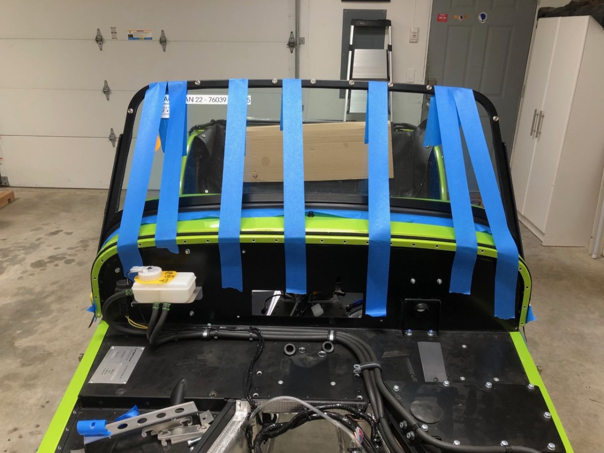
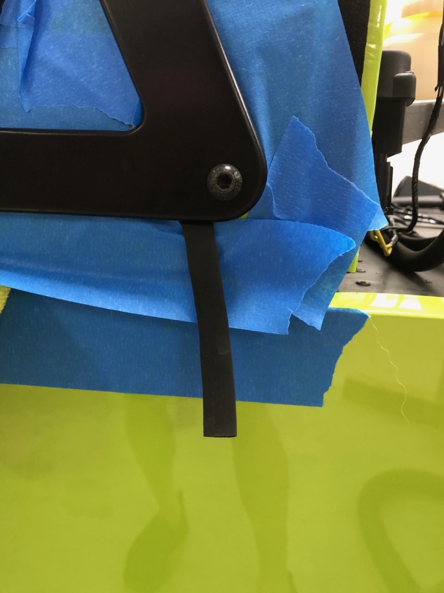
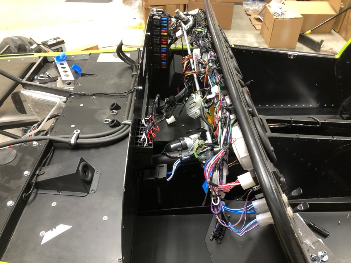
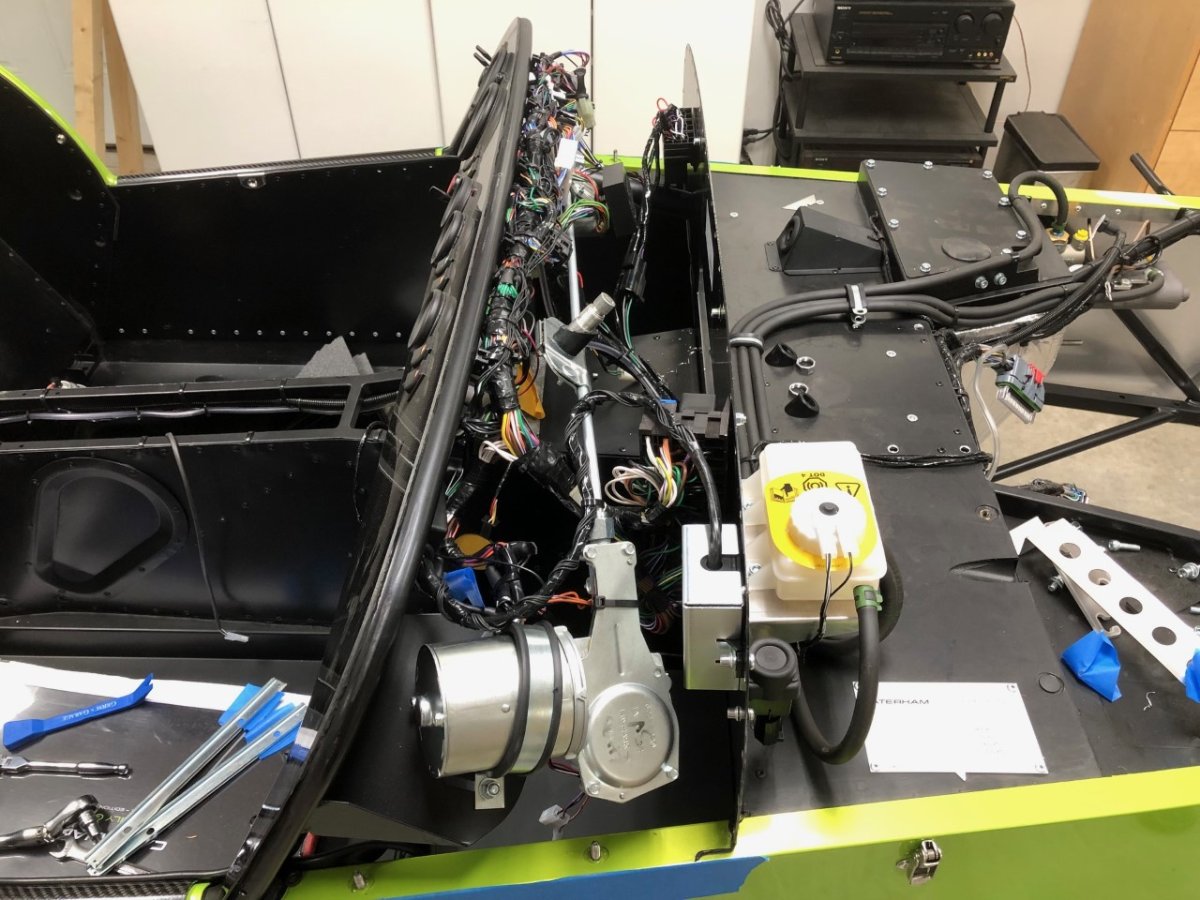
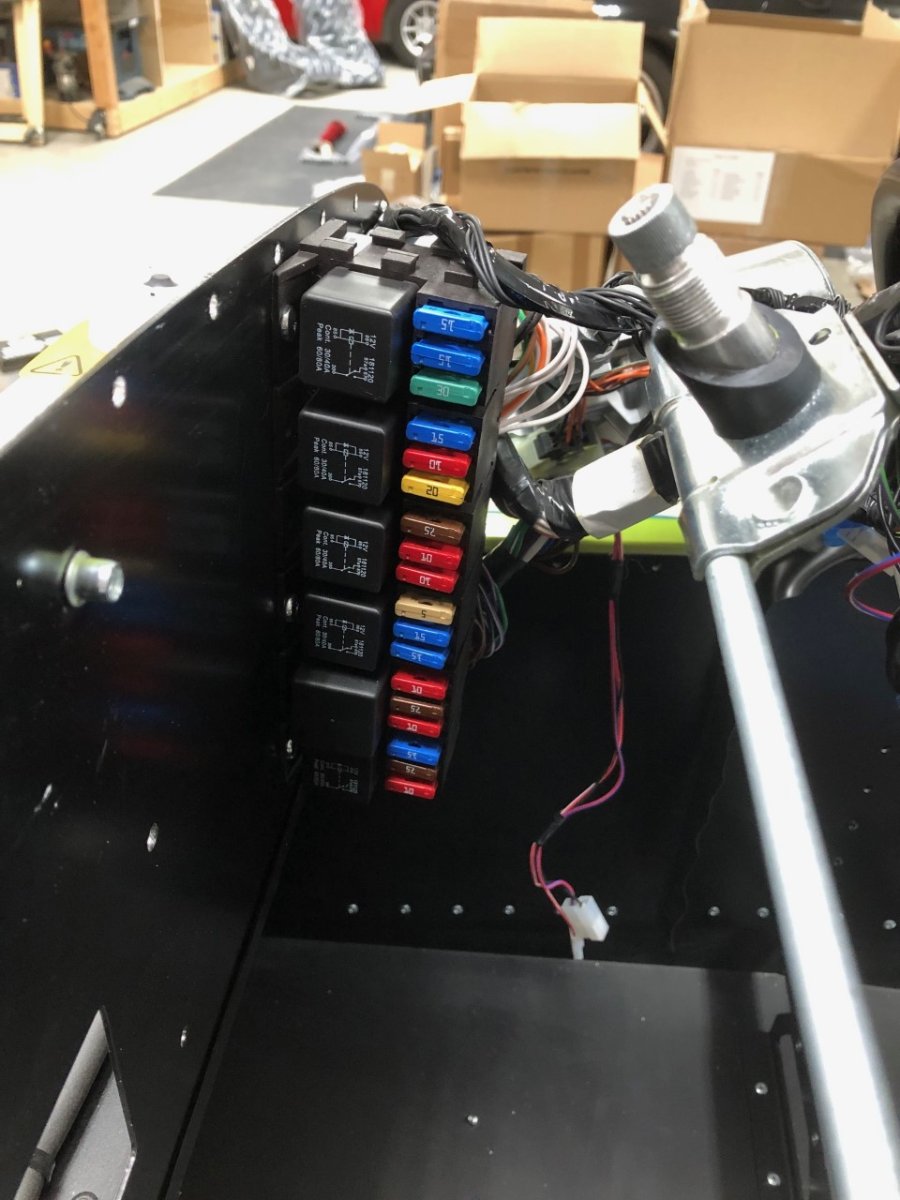
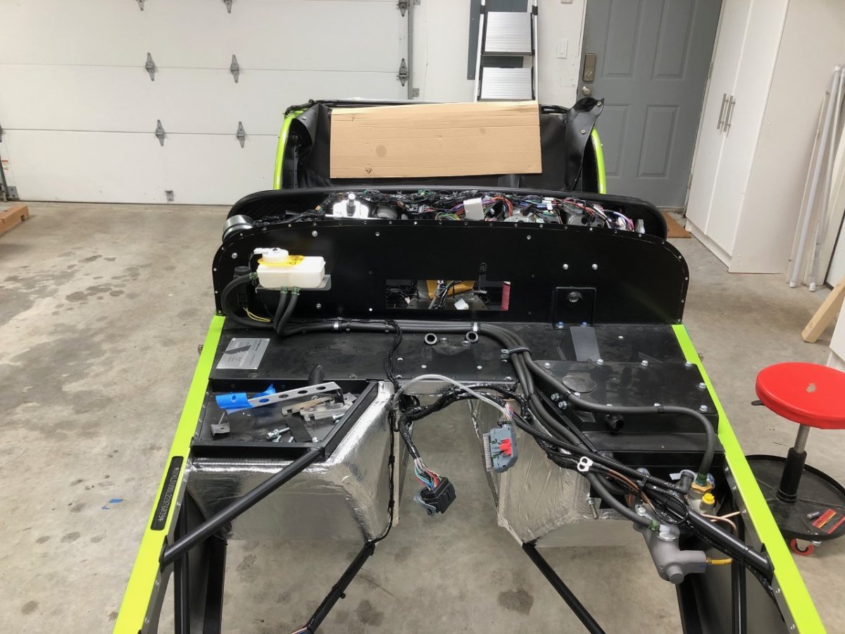
Thanks to the help of a few people on the forum, I was finally able to remove the scuttle. See thread I linked to above for details if you tackle this yourself in the future. Since I was doing this solo and wasn't sure if the windscreen would attempt to tip backward once the 4 securing bolts were removed, I burned through a bunch of blue tape and had a razor blade handy to cut them when I attempted to lift it off. Worked flawlessly. Probably the only time I'll say that throughout the entire build. For some reason, the factory didn't trim the windscreen rubber on either side. I can take care of this now that the windscreen and stanchions are removed. Wow, that's a lot of wires to undo! I'm still waiting for my 620 dash wiring sub loom to arrive which will replace a chunk of them, and the AiM will receive signals from the ECU for all the gauges, so most of those wires will also go. CAN will make this much cleaner. With the scuttle removed, I'm left shaking my head at the fuse box. It seems that a contortionist will be required to reach several of those fuses. Once I understand how the cover is supposed to fit, I'll see if there is a way to reposition that for much easier access. The Westfield mounts them under the bonnet in front of the scuttle, which makes for much easier roadside fuse replacement. -John
-
I confirmed that with sufficient blue tape to prevent the windscreen from falling backward and protect the scuttle paint, removing the windscreen is indeed a one-person job. For anyone doing this in the future, items to remove are: 26 rivets at the front of the scuttle, plus 2 more on the sides 4 scuttle retaining nuts that attach the scuttle to the chassis tubes Windscreen wiper arm nuts Windscreen washer tube The two screws in the pair of tonneau snaps on the top center of the dash Wiring loom connection box secured by Velcro to the underside of the scuttle near the tonneau snaps Two heated screen wires located at either end of the windscreen. I was unable to remove the grommets, so resorted to cutting off the connectors. I'll probably replace them with bullet connectors that can slide through the grommet to make that process easier The windscreen with stanchions You will also need a lot of blue tape and a Guinness to steady your nerves. I'll add more pictures in my build thread. -John
-
Thanks @sltous, @11Budlite confirmed he also removes the windscreen first. I read in someone's blog they recommend three (no, not a typo) people be on hand to remove the windscreen. I might take a shot at doing it solo later today. I think I can stabilize things enough with tape and cardboard that if it proves problematic doing it myself, I can get the windscreen safely back into place without damage. Famous last words... -John
-
If an M4 rivnut will fit in that location, I'm going that route. The M4 button head diameter is the same as the rivet it replaces, so aesthetically it's a wash, and the M3 heads are a little too easy to strip in my experience. But then again, I'm a klutz. I removed all the other things holding the scuttle in place: heated screen wires, wiper nuts, washer tube, some electrical box velcro'd to the underside, etc. However, it appears removing it is a two-person job given the various bits that are in the way. It will either take a lot of simultaneous maneuvering from both sides, or the windscreen needs to come off so the scuttle can flex a bit to the sides and clear everything. I suspect some cars are easier in this regard given the hand-built nature. The Westfield, in contrast, is a one-person job. Unbolt everything and lift straight up. -John
-
I didn't realize there are two more rivets that attach either side of the scuttle to the dash tube (thought those were small dome head screws.) @sltous and @11Budlite how did you handle that? Can you put a rivnut in that tube? Thanks, John
-
Westfields from that era should have the chassis number stamped on top of the lower tube located directly in front of the engine. The i indicates it's an IRS car, not a live axle. Does that match the information you have? Cheers, John
-
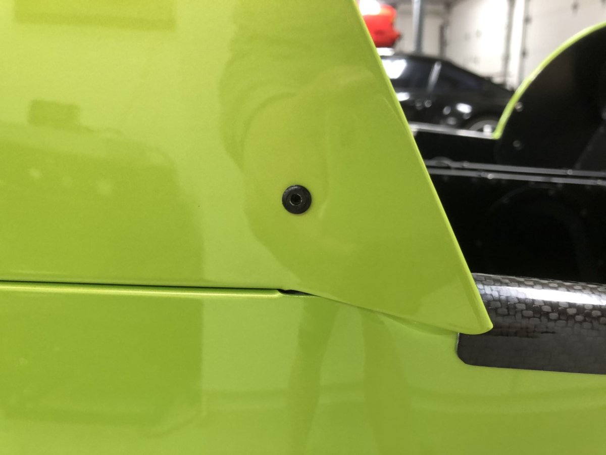
I spent 10 minutes in the garage drilling out the remaining rivets. The first 19 went smoothly, but the next two left the rivet head in place. Carefully scribing the paint around the circumference followed by a slight tap was sufficient to knock them off without any damage. Glad I didn't have to attempt that for all 24. I'll update my build thread later once the scuttle is removed. -John
-
I just ran down to the garage and confirmed I've been over thinking this and hyper-paranoid for no reason. With blue tape covering the rivet area, followed by running my fingernail around the perimeter of the rivet to ensure a good seal with the tape, then using a 3/16" drill bit at very low speed, the 5 rivets I drilled out came out perfectly with no paint damage. I'll finish the job later and takes some pictures. Thanks again to those who responded! -John
-
Thanks @11Budlite, it sounds like the current paint is thin enough to avoid coming off in bigger pieces like @sltous saw. I'll give this a shot later today with one rivet and see what happens. If the flaking encompasses too large an area, I may pick up a leather punch as per @IamScotticus's suggestion and use that to score the paint immediately around the rivet head. The scuttle is definitely coming off one way or another, I just want to avoid visible damage. Thanks, John
-
I don't trust myself doing that 24 times without error, and this paint is not something I can easily match with auto touch up paint. It's a pearl that is only offered by the factory as a paint-to-sample upgrade from their back catalog. If I do need to grind down the remaining rivet heads, I'd prefer to do so with a depth jig using a shallow pitch drill bit. It feels more consistent and takes a shaky hand out of the equation. Thanks, John
-
Thanks @sltous, I'll let you know if I need anything else while your scuttle is off. @IamScotticus the leather punch would certainly be safer and cleaner than razor blade to score the paint. Hopefully I'll hear from Bruce soon since he went through this recently with Croc's car. Searches on Blat Chat haven't helped. In the results I've found, people simply state "drill out the rivets." It makes me wonder if I'm overthinking this or too risk averse. If the paint wasn't fresh or hard to match, I'd be more prone to experiment, but after waiting nearly a year and a half for the kit, I'd rather not rush into an Oops moment in a visible spot. Thanks, John
-
@sltous thanks for going to that extra trouble. I just made an attempt at scribing around a rivet and it's a lot harder than it sounds. Even with lots of blue tape, no way I'll get through 24 of these without some slips and gouges on the fresh paint. I know Bruce Beachman did the rivet removal on CatKong and I've asked him to confirm the process. At the end of the day, building a simple depth stop jig and using a drill bit the same diameter as the rivet heads (5/16") might be the best combination of speed and damage minimization. -John
-
Thanks @sltous, this helps. I toyed with scribing around each rivet but that seems like a lot of work that may not be necessary. Did you get chipping in the paint when the heads spun loose? If so, was it minor and sufficiently close to the rivet head that it could be easily covered by the fastener head or a washer? Those are the same rivnuts I'm planning to use. I hadn't considered plastic screws but also haven't looked at how the rest of the scuttle bolts to the chassis. Something to consider for my McMaster Carr order. Thanks, John
-
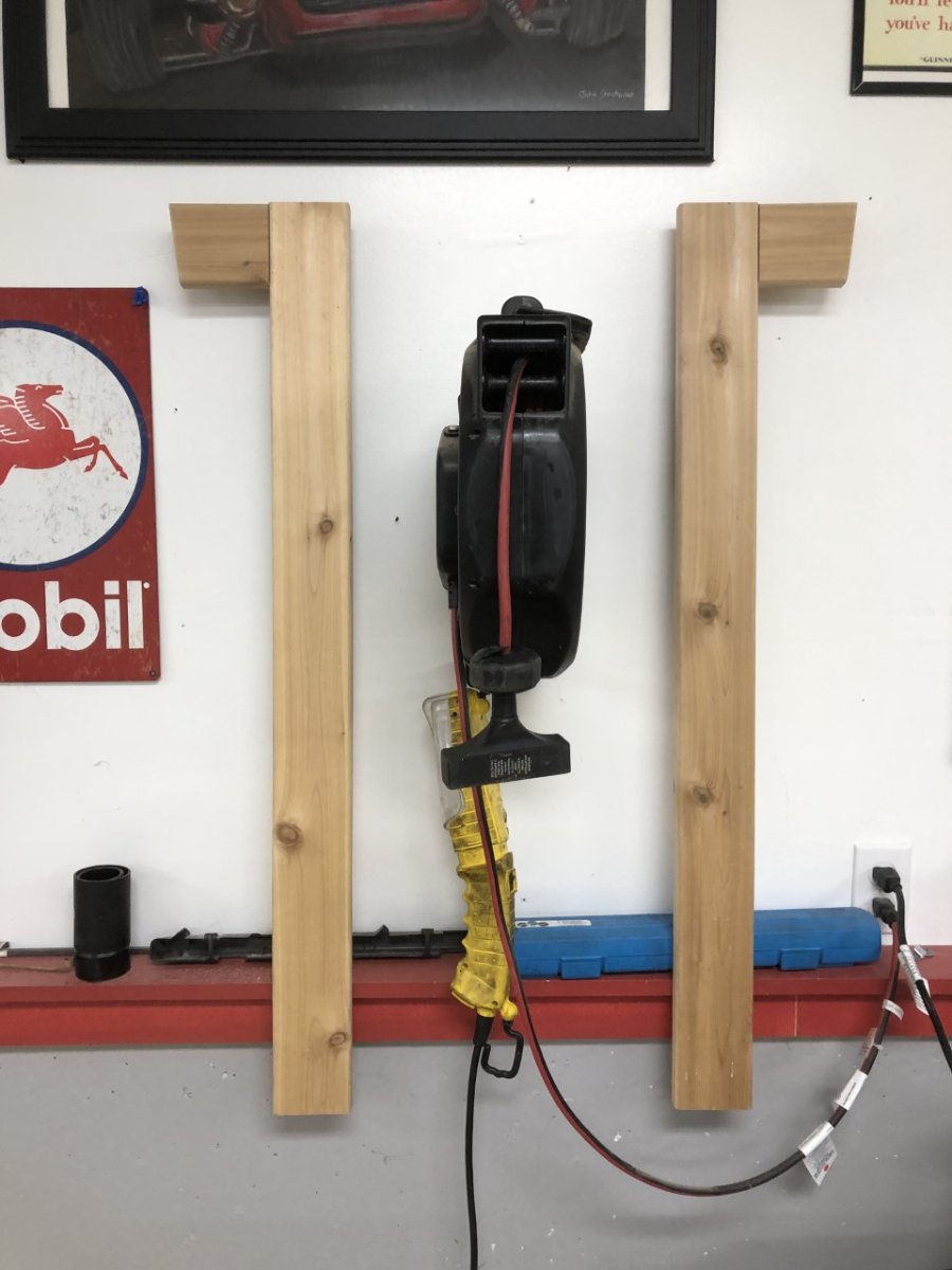
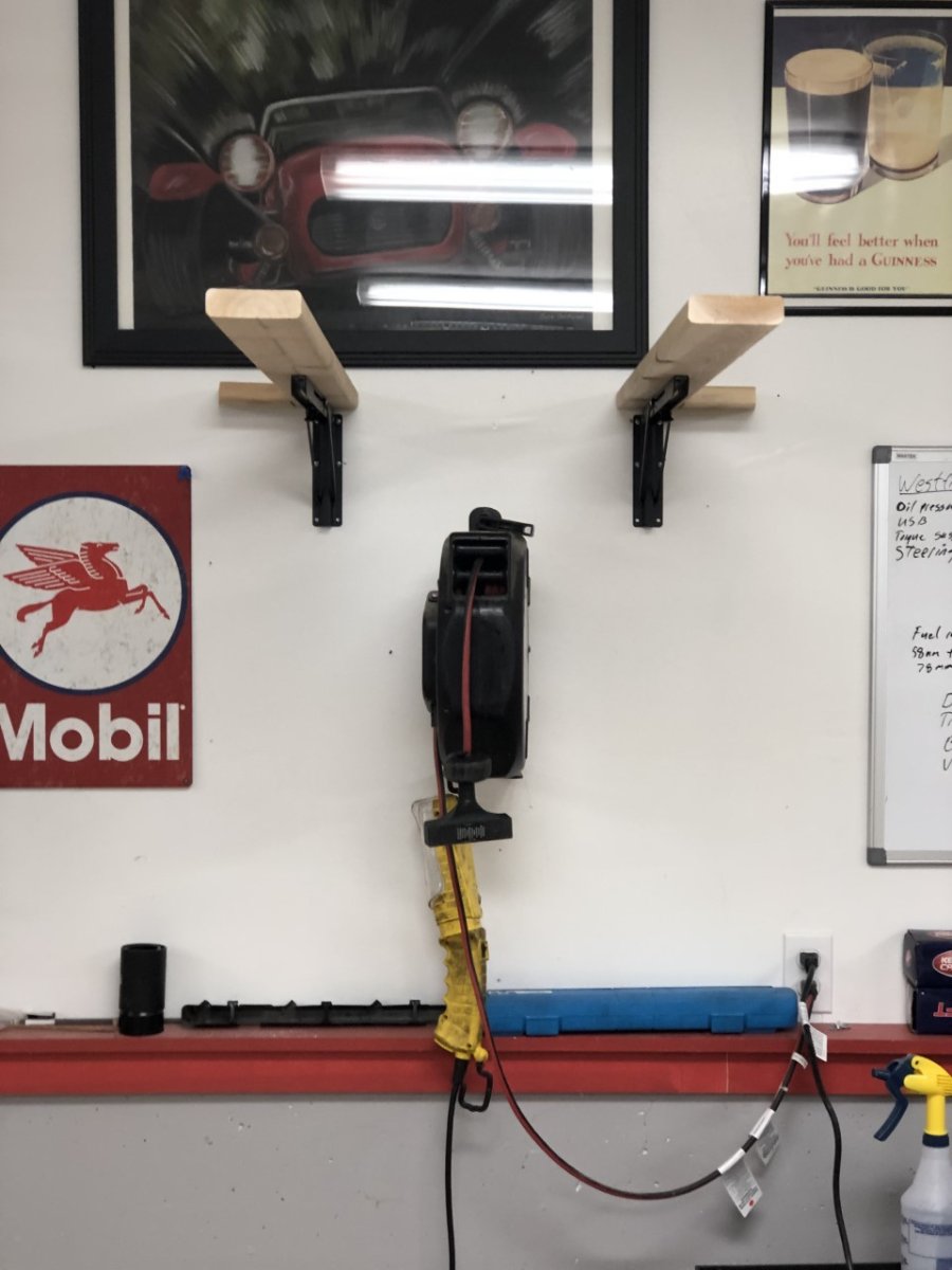
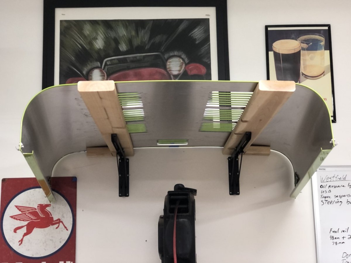
I've been sidetracked. Consequently, no progress this weekend, but I do have a couple of updates. The nice thing about the Westfield's fiberglass body is the bonnet is sturdier than the Caterham's aluminum version and the color is in the gel coat. Therefore, no paint to scratch or fear that the bonnet will deform simply by looking at it wrong. Consequently, removing the bonnet was less fraught with concern and I never worried about simply placing it on the ground when performing maintenance. Not true with the Caterham. Taking a page from this thread, I made a set of foldable arms to store the bonnet when needed. I still want to add a little foam or bubble wrap to the faces to increase contact area and further protect the bonnet's underside, but otherwise it's done. Although I forgot to weigh the front CORE/Hyperco assemblies before installing them, I did weight the rears to compare those to the weight of the factory Bilstein/Eibach coilover; a combined savings of 5lb 4.8 oz. Given the fronts are smaller and the Hyperco springs are a larger diameter than the Eibachs, there is less weight to save on that end of the car. Assuming the savings is about half that of the rear, it's still close to an 8 lb system saving. Plus, the COREs mount upside down, further lowering unsprung weight (see photos in previous post). To make my life a little easier now and in the future, I'm making the scuttle removable. I started a separate thread about the best way to do that here. If you've been there/done that with this mod and have guidance on the best way to tackle removing the old rivets given they are painted over, please reply there. Thanks, John


.jpg.1b1c5589b65565f6b4974263ce8296bd.jpg)