MV8
-
Posts
2,297 -
Joined
Content Type
Profiles
Forums
Store
Articles
Gallery
Events
Library
Everything posted by MV8
-
I guess this is all the time and not engine temp or tps dependent. Try moving the plugs around too or simply replacing (check new plug gap). Are you using the rpm drop test of disconnecting each coil while idling? Jiggling the wires where they meet the coil connector since they can get loose? Just fyi: There is an extender for plugs buried in the head in order to use an inline glass tester.
-
This is fully manual hi and lo using the heater blower control and powered by the alternator directly, with no mods in the cowl.

-
I'm saying if the fan or fan and relay has all power routed through the 10 amp htr fuse, it should blow if the fan is operated at all unless some other voltage source is jumpered on to the circuit that includes the fuel pump and instruments, which could also cause it not to shut off if that source is constant and not switched. However, if that were the case, the instruments and fuel pump would continue to run also. You can use the heater control as a control for fan speed with two relays if pin 30 is powered by another circuit such as the alternator B+ stud. I can draw a circuit like that if you'd like.
-
How is it wired exactly? I'm confused about what the benefit of the relay is if all 21 amps flow through the htr control, assuming htr low or high is connected to pins 30 and 86 (15a plus the relay coil), with the other speed direct to the fan motor (6a). The heater shares the same FS2 fuse with the original fuel pump wiring and all the instruments. This should be a 10 amp fuse (very weak htr blower by modern standards) so you must be applying power to pin 30 from somewhere else. I have electrical experience in a many fields but I'm no EE.
-
I went ahead and made a diagram as if you had an electric fan originally and just want it to work automatically with the original wiring and thermal fan switch. You need some 12ga "primary" stranded copper wire, an inline ato fuse holder, a 25 amp ato fuse, a standard 4 or 5 pin relay 25 amp or larger or a typical fan kit that includes a relay that can handle at least 25 amps, a 12ga (yellow) eyelet terminal that will fit over your alt B+ stud (probably 5/16?), 12ga butt splices, four or six inch black zip ties, good crimping or soldering skills, and some electrical tape though heat shrink would be nice. It will act like a one speed, 1450 cfm fan.
-
I think you are talking to me. I'm Steve. Whatever you are connecting the red wire to has power when the key is off so not good. Can you take a picture of the front of the engine and back of the radiator area? Do you want the fan to come on automatically, with a toggle switch, or both independently since it is a two speed fan? Do you have a spot for an extra temp sensor on the engine or radiator?
-
The derale 16212 is a great fan. I have the same one on my geo tracker with a s10 v6 driveline swap. It looks like you have the red wire capped and are only running power on the grey wire. It is a two speed fan. In order to get high speed (1450 cfm), both positive leads must have power to pull the full 21 amps versus 15 amps and 1000 cfm. Obviously, it would be a lot more effective direct mounted behind the radiator. It would be tough to make efficient baffles/rubber ducting behind it with everything in the way plus it is partially blocked at the bottom. If you turned it 90 deg it would help. The good news is that fan is powerful enough to be used by itself with no engine driven fan if you can get it close or direct mount. How did you know my name was Andy? (I'm kidding! I'll stop "helping" now.)
-
My pleasure. I enjoy problem solving.
-
Yes, my conclusion. "Trust but verify" before plugging into anything.
-
The white 3 wire connector is the 94 and older heater plug. Caterham has a subloom/adapter for use of the 95-up heater. The wwp looks to be a 90's vw part but without the check valve. Might be useful if you need to source a connector if there is no pigtail. This connector type should have a wire around the edge. The pig tail for the wwp should break out near the filter but is probably about two feet long. I've seen pics of different wwp reservoirs in various locations.
-
I don't have a 05 schematic. The white plug middle terminal on the three hole side (green wire) should be the one to the washer pump positive. The orange is the positive feed to the washer control. The washer connector should have a black for ground and the green wire. It should split out of the main harness near the air filter.
-

Hydraulic clutch set up for Crossflow w/ Rocket box Seven
MV8 replied to Vinman1's topic in General Tech
There are several different ways to do it. The easiest, most cost-effective thing you could do would be to fit the cable and weld on the brkt but I understand why you don't want to mod the chassis. Fitting a slave to the original fork is probably not an off-the-shelf package you could buy. It sounds like you probably would be better off with an all original type slave system. It's possible the original cable brkt was removed to convert to hydraulic. -
If there is rust, it can insulate the jacket reducing thermal xfr, damage the pump seals causing a pump leak, clog the tiny holes in the head gasket, and block rad passages. If rusty under the water neck, I'd use evaporust thermocure and water for a week with no other changes, then thoroughly flush with water, replace the pump, install a 180 stat, back flush the old radiator, then refill with 50/50 standard green antifreeze (no "long life" coolant). If it still runs hot, replace the radiator.
-
The copper brass rad is serviceable, but radiator shops that can do the work are few and far between and the cores are more than a new aluminum radiator. All radiators collect sediment in the lower tubes that will eventually clog more and more of it. You can check during warm up by hand, feeling the core for uneven temps. Back flushing is about all that can be done on the newer radiators.
-
Did the car have muddy coolant when you got it? What model fan did you install? A few pics would be great.
-
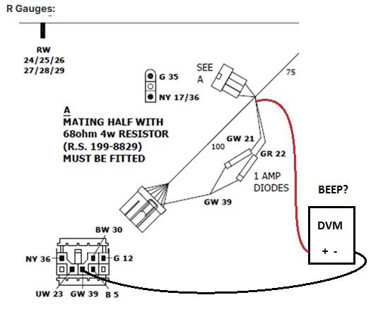
I think you've figured it out. The diode polarity on GW does not match the drawing provided by Caterham. Note the rings on the diodes in the drawing are toward the connector.
-
Does it beep with the meter in this config?
-
I don't know your experience level with a dvm but your response seems unclear. Select the ohm position, plug the leads into the appropriate sockets for check ohms, place the leads together to show continuity or beep to ensure it is working before trying to check anything. You can back probe the connector then use a thumb tack to penetrate the jacket over the splice to check each diode separately. I think the resistor is related to the operation of the speedo.
-
I don't know the tach logic. I have no first hand knowledge; only a seven year old layout diagram (hesitant to call it a schematic) that does not show everything and what you provide. I went through the 2015 diagram and made a simplified flow diagram just for the TS (haz off). Your owners manual will show the location of each relay and fuse on the socket panel. I call it the HAZ relay but it may be called something else. It sounds like a reversed diode but I need to absorb all your updated information. I think the other lumps are not diodes but splices. I assume the diodes are so the brake filaments can work with the hazards but not back feed the turn signals, which would cause all the indicators to come on when the brake pedal is applied.
-
Looking at the available information, generally, for the TS function, flasher output (typically LGK coded wire) is through the hazard SW (LGN), then the hazard relay (LGN), then the TS SW (LGN) to the left (GR) or right (GW) with the extra wire in each terminal going to the tach for an indicator. The flasher has constant B+ and is always ready for a load. The hazard relay is powered in RUN. Switching on the hazards bypasses the hazard relay so it will work with or without the key. This is a best guess.
-
I think Caterham has been tight lipped about schematics since 2015 which only hurts customers while doing nothing for their bottom line since the schematics are not offered for sale. The "right to repair" is it's own subject. I think the DCM is probably just a way to build a single harness for all dash options and not the problem. How about a pic of the relays installed? The sockets for the relays and flasher are standard five pin orientation. The flasher has three pins and will fit in a relay position. It is possible you have the hazard relay swapped with the flasher.
-
What happens when you try the ts sw in the config they sent a pic of? I'd request the main harness schematic that includes the hazard and turn signal systems, check the operation of the hazard sw, and check the wiring arrangement of the hazard switch against whatever reference you are using. Can't read your email links to R and S gauges.
-
They must have factored in the expected inflation rate between now and delivery. How many clowns does it hold? Just kidding! Imho, good engineering from what I can see from the cheap seats.
-
WTB Bushings for solid rear axle Caterham (1984)
MV8 replied to ChuckM's topic in Parts For Sale / Wanted
Thanks. I think originally the 636 and 2030 were from a very light duty, narrow leaf spring vehicle as the press-in eye bush and migrated to an industrial part when the supply dried up. It is not hard to find similar sized eye bushes but the length is always at least the width of the narrowest, currently common leaf springs today at 1-3/4 / 44.5mm. An actual "bushing" (versus essentially a round motor mount that can twist a few degrees) that is free to rotate would be much better; easier and cheaper to replace. An experienced machinist could quickly (cheaply) turn plastic inserts to fit with flanges or thrust washers from about $20 worth of rod stock and a set of spares while he's at it and no wear to his tools or a short production run. I don't know if 3d print would be suitable. Burning out the rubber is the worst part. -
I like the old S8 for obvious reasons.