MV8
-
Posts
2,303 -
Joined
Content Type
Profiles
Forums
Store
Articles
Gallery
Events
Library
Everything posted by MV8
-
Me too, but it was hardware included with a greddy turbo kit for a miata about 20 years ago, holding the td04 to the manifold. Bolts had no head marking. I guess these bolts were new replacements and not the originals?
-
That would be a very unusual 1st ratio of 2.37 with a 3.9:1 diff and a 22.97 tire od at 8k. There is a close gear set available with a 2.97 1st (51 mph) and the domestic production Merkur T9 has a 3.36 (41.7 mph).
-
What rear tire size?
-
Inch/lbs, not foot/lbs. Only main, head, and connecting rods are foot/lbs. Go for mid-spec rather than peak spec.
-

Hydraulic clutch set up for Crossflow w/ Rocket box Seven
MV8 replied to Vinman1's topic in General Tech
The starter is on the opposite/curb side for a hydraulic clutch. Why change it to hydraulic? -
R888R are available in several 13s and a 185-60-14 that may work for your rim width.
-
3.5mm is about the same thickness as a mens leather belt and the engine would likely rock that much under load (amazing to see how much engines move in cars strapped to a dyno). You could shave 1/8 off the bottom of the engine brackets and use a washer if you ever needed to go back to softer mounts. Less vibration with the original jag mounts. These are just higher durometer from the carbon powder mixed with the rubber. Have you considered a loose at idle, limit strap across the left jag mount to prevent too much movement yet still provided the normal NVH? Do heavier, more powerful xke jags have mount issues? I've not looked into that or what that group does about it. As rubber mounts age, they tend to harden (less movement-more vibe) and crack. I'd replace them if over 20 years old; especially at under $10/each.
-
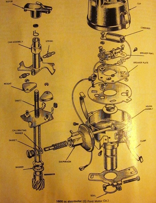
Here is a diagram of the earlier points type distributor showing the weights and springs. I found it in one of my Motor manuals printed in the '60s. The electronic type is very similar.

-
C18556 for a '60s Jag XKE https://www.oreillyauto.com/detail/c/uro-parts/engines---transmissions/mounts/motor-mount/31470ece703c/uro-parts-engine-mount/uro0/c18556/v/a/15662/automotive-car-1967-jaguar-xke?q=motor+mount&pos=0
-
10deg btdc, which is typical of most engines but I'd run 12 or so if there is no detonation on your hills with your fuel quality. If there is no mark and just a pointer, you can add a mark for 10 on the pulley using a couple different methods to be accurate or use a dial-back timing light and the tdc mark. I expect it is a standard electronic ignition, vacuum advance, centrifugal advance distributor for a euro market escort with a 1600 that is the basis for the Super Sprint 1700 dual carb, which has no provision to connect the vacuum advance to "ported vacuum" (provides no suction at idle or WOT). The vac unit rotates the breaker plate and fills a hole in the side of the distributor so to remove it would require a few small, hard to find parts or ingenuity. I'd leave it be. I also expect the 1700 spec distributor uses softer springs on the flyweights or in keeping with tradition, one of the two is simply removed for the additional benefit of "adding lightness". Regarding the off idle bog, make sure the rotor rotates by hand a few degrees easily and springs back. If it doesn't, some work is required to clean the weights and lubricate or change/remove a spring. If the distributor seems ok and has little to no discernable shaft side play, It is likely your carbs just need a thorough cleaning.
-
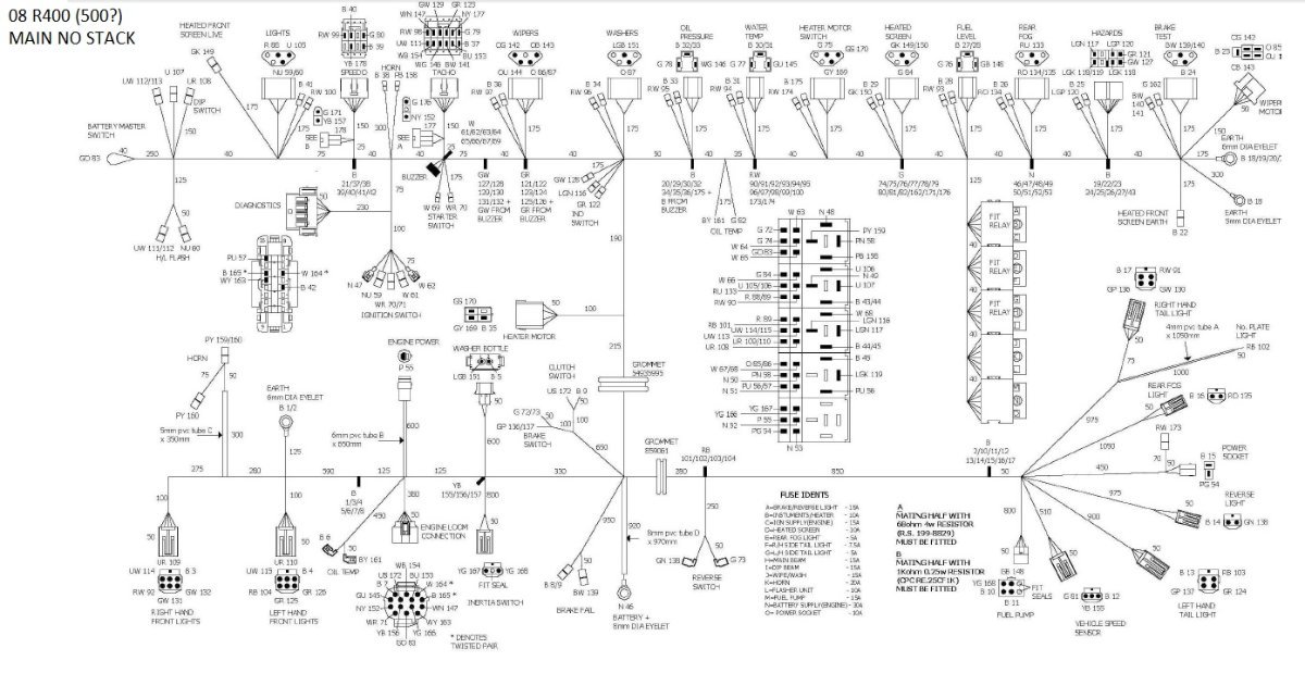
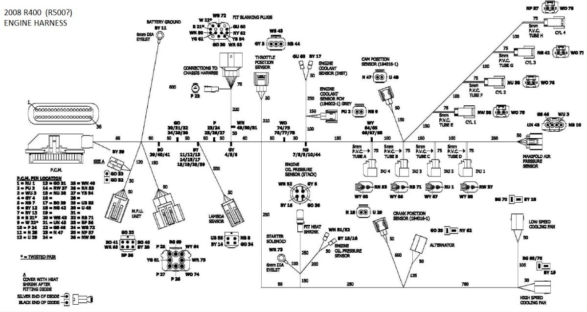
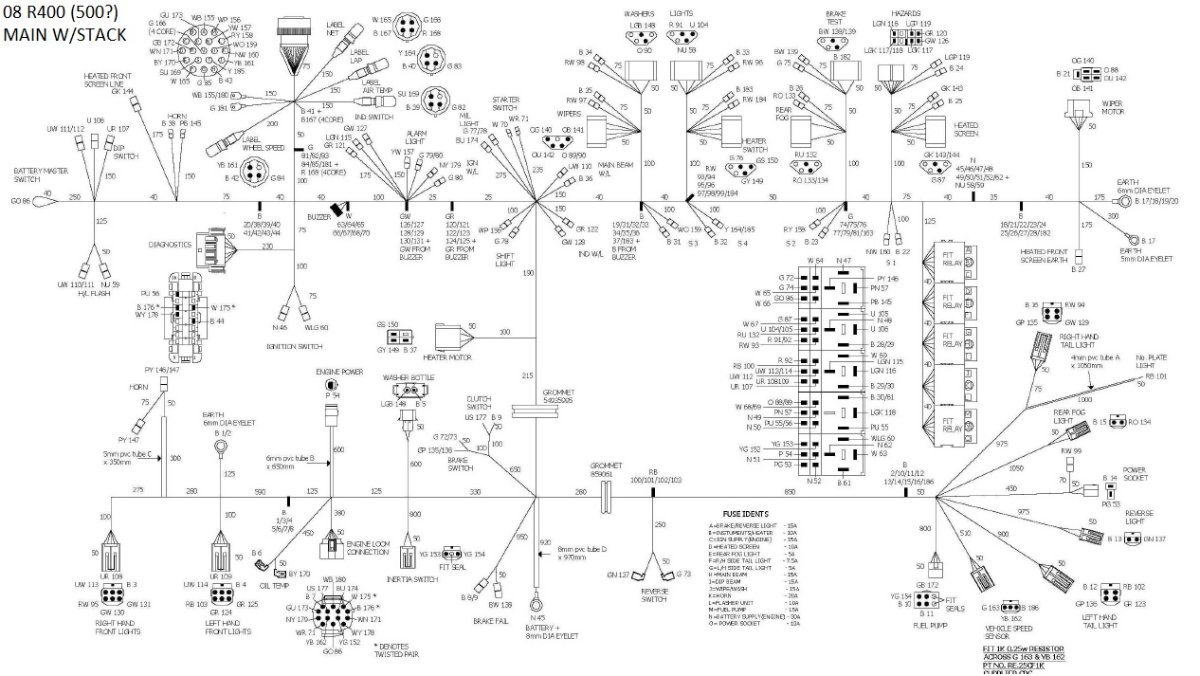
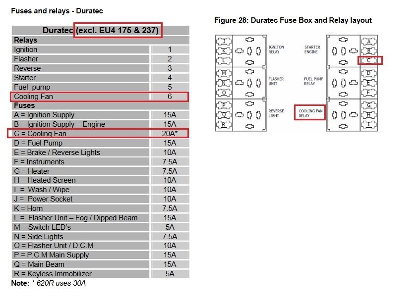
I think the schematics are the same for the '08 R400 and R500; both duratec powered. Here ar e the '08 R400 schems.
-
I'd search triumph forums, posting WTB early triumph wheels to maximize responses then filter. Don't be too specific. Easier to find across the pond. These look like a good restorable set, even if shipping is high. https://www.ebay.co.uk/itm/255469261321?hash=item3b7b279209%3Ag%3A4-4AAOSwBP1iSYnn&LH_ItemCondition=4 I think the wide slot version is correct for the S2. Not sure where you can find the lotus specific hub caps. The 5.5 is much more common and could be narrowed. There are specialty shops that do wheel modifications but they usually are cutting the welds that hold the center and fitting new hoops/rims. New hoops without centers can be bought for mini stock racing but not that narrow. http://www.diamondracingwheels.com/index.php/racing-wheels/mini-stock-series Very time consuming to narrow without putting the hoop/wheel in a lathe or using a rough cut then milling as needed. Make sure you can find tires to fit the 3.5" rims before swearing off the wider S3 sized rims as unacceptable.
-
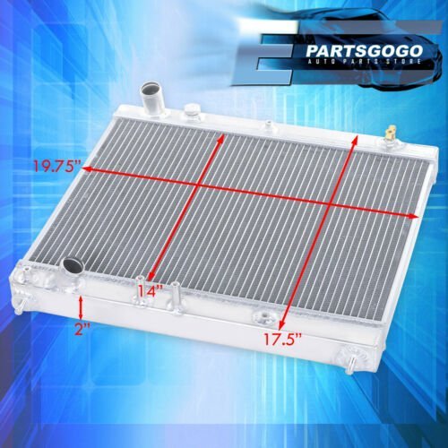
Baffles would be a big improvement. It looks like a lot of the airflow through the grill goes around and over the top of the radiator. Also, the fins are not parallel to the airflow and the core thickness makes it more restrictive to airflow. There are specially made cores for sloped mounting to keep airflow parallel to the fins and tubes. The one piece tilt front end and aftermarket radiator with no flanges on the sides makes it more difficult to seal. I'd probably make a tunnel out of .050 3003-h14 and pop rivets that attaches to the chassis and use silicone baffle material from aircraft spruce to rivet to the tunnel and lay over the edge of the radiator, so air pressure pushes the material against the radiator to seal. I'd be tempted to swap in an aftermarket scion radiator like this one with a larger core and vertical but it would take some fab to adapt with consideration for the pipe locations and angles. The pics on bringatrailer are not good for determining the best way to duct air to the rad. Mainly, without swapping parts, I'd pull the shroud, try to move the radiator to be more vertical and parallel to the airflow, and either duct between the rad and grill or fit a wall on the chassis behind the rad with a bulb weatherstrip against the tilt bonnet. Use card board to make patterns for the sides and top. I can draw some ideas for baffles on good pics of the area.
-
There are pics and vids of Vipergeek's car on bringatrailer. The intercooler is right in front of the engine, behind the radiator. I use the highest amp fan I can find for the radiator core size. Amp draw is a great indicator when cfm is subjective. I like the hayden ultracool two speed fans that draw about 23 amps on high. Oem primary cooling fans for high output or displacement fwd applications typically pull 30-40 amps. The m142k pulls about 17 amps. On Vipergeek's car, I would remove the aluminum shroud between the fan and radiator in order to direct mount. The shroud is an attempt to improve fan efficiency but it is restricting flow through the core in the corners. Oems typically use rubber flap "check valves" with such a shroud so when the fan is creating a lower pressure inside the shroud, the flaps are closed. When air pressure is higher inside the shroud (such as driving over 60 mph), the flaps open. I'd also move things around on the shelf and wall to make some space to fit the largest volume expansion tank possible to add to the pressurized system volume, completely fill it (versus half way if no oveflow tank), and move the overflow tank as needed. It looks like it could hang off the left upper rail in front of the brake master with a base plate. The ecu and connectors take up a lot of space on the shelf.
-
What info is on the package? The main gaskets should interchange. Some kits cover both.
-
The prints look great. You guys also have the option of sand casting. Small parts don't need a commercial foundry and generally don't need machining. Probably have some hobbyists in your area who would do it for fun and a trade. Old bent alloy rims make fine ingots. Lost foam process is even better for detail.
-
Amazingly reasonable State. My State refused to allow me to register my GO4 Interceptors because "they look like a golf cart". Had to eventually complain to the Governor's Office on that one. These are production vehicles many states (including mine) use on highways and are not "low speed vehicles". I prevailed mostly because they had no argument.
-
I'd replace all the hoses with braided if they are not already. If the pistons and bores are in good condition, I'd just replace the seals. Ditto on the wheel cylinders. If the master reservoir is plastic and brittle, I'd get a new master that includes it. I'd definitely fit an adjustable prop, which is much better than no prop despite being 50/50. Variables are prop valves but with an adjustable preload on the internal spring. Install it where the driver or passenger is not likely to turn it out of curiosity. Once satisfied with the adjustment, mark the position down the side and leave it be. Oem valves are typically combination valves with a fixed prop valve setting and a metering valve to apply the rear before the front to overcome the spring tension holding the shoes away from the drums, similar to residual pressure valves. If you ever suspect brake issues, a test kit is about $50 and includes adapters to fit various bleeder threads.
-
Removing water marks from carbon nose and cycle wings
MV8 replied to das76's topic in General Sevens Discussion
I'd soak paper towels in vinegar and spread over the fender and wait a few minutes, then it will probably come off with a light touch from a plastic pot scrubber. Try a small spot first. To be easier to clean, maybe try a rustoleum aerosol eggshell/satin clear coat after they are pretty again, with acetone prep to remove residual vinegar. -
I doubt you need a new HLA. Is the plunger falling out? Vaseline or a little grease. Suspect out of round on the end from being dropped or stepped on? Hold open end against open end of a "good" HLA to see if they line up, rotate one 90 deg and recheck or use a cheap 6 inch dial caliper from princess auto/hbf/ebay. Not out of round and the plunger is not falling out? Is the head bore nicked or gouged? Will a "good" HLA from another position go in ok or does it do the same thing? Are there little shavings or any roughness in the bore? How about a pic? You could buy a complete rebuilt or used head. Don't worry about spongy.
-
Just an fyi, but the HLAs are very sensitive to the oil viscosity to stay pumped. They came out with a larger hole design as a bulletin from Mazda but as long as you stick to 5w30, it's fine.
-
The Regular Summary of Classified Ads of Se7ens Found For Sale
MV8 replied to Croc's topic in Cars For Sale
That's really tempting. Then I realize I don't live in an emission testing area to benefit from the year of production and could scratch build for less effort than the resto and I'd want to make changes which I would be conflicted about. Great to see original details in the pics, though it looks like at some point he had the expansion tank moved back for access with the nose on. -
Some questions you will likely get about the mild hesitation at 3k: Already a steady 3k then accel from 3k (delay/slight bog) or starting off-idle passing through 3k and it stops pulling as hard (flat spot)? Using WOT or part throttle? Racing or touring/road car (leaner mixtures)? All those things are factors and most components have overlapping functions, varying effectiveness based on flow/rpm, and easily throw each other off somewhere in the range. Complicated to say the least and easy to make some aspect worse in the process of making a minor improvement. Make sure they document the existing parts (and keep them) so you can go back if you want to later on.
-
I believe they are sourced from the jag xke. C18556 is a part number for the jag.
-
While the arrangement is not the same, it looks like a 310 (duratec) has a total of six relays and a 20 amp fuse for the fan.