MV8
-
Posts
2,303 -
Joined
Content Type
Profiles
Forums
Store
Articles
Gallery
Events
Library
Everything posted by MV8
-
I'd ask how many more standing orders are needed to produce the scoops "soon". You can always resell them here.
-
Also, with the compact setup off the alt, you could run one additional wire along the harness for fan operation only in RUN, jumpering off the main relay 87. I doubt the fan pulls more than 15 amps. You might try tugging on the blk/grn a bit. It may only be a foot long or be a foot short of the normal bank of relays.
-
Since the valves were not skimmed, I would lap a couple intake valves to see how much work it is to remove the marker on the seat with a dab of grinding compound on the valve. I suggest the wood dowel suction cup rather than a suction cup on a drill. Get campy like you are trying to start a fire, rotating the dowel against opposite palms. Oil or barely grease the stem where it will be in the guide. Never hurts to check the machinists work. I would expect a great deal more care and more eyes ensure machining setup is correct on a production run than on piece-meal work.
-
The checks (with the battery disconnected) should include all relay terminals and the tach and speedo secured relays, then the ecu connectors (ecu unplugged), all the fuse terminals (unless you already checked that all the fuses have power always or in run and not just if they are blown). If all that fails to find continuity (ignore color codes), you can add a compact system at the fan with new wire, a sensor and relay with an inline 10-12ga ato fuse holder to the alt stud or open the harness covering to find waldo and retape. You might start near where it should be with the other relays and fuses. Sounds like they cut out the typical circuit and forgot to add it back in for the ecu control. Your pics are very clear but maybe pull back some for the overall area so we could broaden our focus. Might help.
-
What are you jumping for the fan to turn (+,-, which wire)? Is it turning the right direction? I'll guess that blk/grn is being jumpered positive and blk is a constant ground. The correct owners handbook should also list an associated fuse that can help you find the relay. What did you find with the ecu pin 33? Why is the engine new? Overheated? I guess you are the second owner? A little back story please.
-
The "schematic" looks like the use is to help customers install a harness and doesn't match your relay config/fuse block like you've said. It does show the fan switch in the radiator and matching connections at the fan and relay. Not really a schematic and also the diagrams are cut-off. The correct owners handbook should show the location of the relay. Do you have a temp sensor in the radiator or is it blocked off/plugged? To find the fan relay, you could disconnect the battery, unplug the fan and back probe for continuity to a relay terminal but you may need the long diy jumper for the dvm leads to reach. What does the fuse panel look like?
-
Once you find the right parts, we can figure out why.
-
Assuming you have the right diagram, ground a clip to the chassis, unplug the ecu, find the right terminal, then touch to ground to see if the relay clicks and/or the fan comes on. Another option is to use your handbook to find the right fuse, pull it, find the side that still has voltage, probe the other side with the dvm set to beep continuity, then back probe the relays. Care to share the diagram? Is it the right one for your car?
-
Did the machinist grind the valves?
-
To save some effort, request from Caterham, a pdf of the handbook that covers 2019 models and a schematic or factory service manual covering the model, which would include the schematics. Another option is to pull and reinstall each relay until you find one that doesn't seem to do anything. Same situ for the fuses. Usually for a dc fan on older equipment, there is a separate, single terminal, coolant switch but there are many ways to do it. The relay may control the positive or the negative lead to the fan. If you feel comfortable and capable with a dvm, paper clips, and a jumper lead (DIY assembly of alligator clips on a few feet of 14-18ga copper stranded/primary wire), I can tell you how to find the problem without splitting the harness open.
-

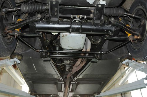
Swap to independent rear suspension on a Stalker?
MV8 replied to rdymond's topic in General Sevens Discussion
Major work and not a bolt-in, with a lot to consider in the process unless you buy an irs frame and associated components. The axles will be custom; shorter than the oem irs donor. I have not converted a stalker. I'm in the process of converting a spitfire to the ford 8.8 irs. I don't see much value for the work involved. -
Lotus Seven Series 4 - brake pipe information requested
MV8 replied to PhilS4's topic in General Tech
Looks like automec kits are ok if you select a left hand drive kit for the German market. Otherwise, it is just copper line; no nickel. https://www.automec.co.uk/ -
I would not assume anything with a one-man operation. How long since he read your message? The FB msg you sent will show if and when the msg was read with a circular icon on the right side. I'd send another msg a week from the read date asking for the status. If it hasn't been read in a couple days, I'd also send an email. No reads or replies in a week, call. I'd want to put my hands on the part before replying. If I don't have any and are not making them, check with my local sources.
-
About the crankcase pressure, is it broken in yet? Is the road draft tube installed and taper to the rear or is the end square cut? Was there a pan baffle/windage tray? Standard volume pump? Thicker oil doesn't drain back to the pan as quickly so you probably have more in the valve cover than if you ran something thinner. Too late now, but a common mod during building is to smooth internal surfaces and radius oil returns to aid flow back to the pan. Glypt was often used to coat internal surfaces for a slick, oil resistant surface. I see you have a borg and beck pressure plate. These have higher ratio levers (5-6:1) than modern diaphragm spring pressure plates (effectively 3.5:1) and are slower to fully clamp the clutch after a shift. I'd try a little more time between foot off the clutch and applying throttle before another tear down. If only we could pump fresh synthetic grease in NOS release bearings.
-
Lotus Seven Series 4 - brake pipe information requested
MV8 replied to PhilS4's topic in General Tech
Not my s4z. Not my boots either. If you need more help routing, take some clear pics of the area we can draw on. P clips ever foot or so generally, gentle bends, cut off 3 inches or so to practice flaring, if bends need to be within 3 inches of the fitting, flare it when straight then bend when assembled.
-
Thank you. I enjoy it. I see Redline is currently active with their latest filing for an address change last month. You may be able to reach Mr. Mintoft on Linked: https://uk.linkedin.com/in/chris-mintoft-356427?trk=people-guest_people_search-card An interesting article: https://www.autocar.co.uk/car-news/new-cars/caterham-seven-old-vs-new
-
Christopher, I believe Scott is referring to Chris Mintoft, the owner of Redline Components, Ltd. https://www.caterhamlotus7.club/news/operational-statement-chris-mintoft-director-redline-components-ltd I have experience in this area too and it seems very simple to me but I agree with Scott that it can easily result in a "hack job" on a first attempt. For anyone interested, the methods described are no hack and may be how they came up with the original scoops for the lower cost, single down draught option (which I would prefer to dual 40s on a touring car).
-
An ecu typically relies heavily on the cts to determine the engine operating temperature. The cts resistance is calibrated to be around a certain value depending on coolant temp. Sometimes they fail by being out of tolerance or if the connection shorts or opens. If the engine is at 200f but the cts says 300f, it will be too lean and more likely to stall at idle. If you know the oem application or part number for the sensor, the chart should be available like this one for GM. Resting means nothing preventing the cam from rotating. Free to rotate to a resting or balanced pressure position on the base circle/least overlap position once the belt is removed. When on tdc for #1, some of the valves will still be open but the spring pressure is trying to close them, so the cam will rotate. It is not unusual to have to force one of the cams to rotate a few degrees to align with the marks when installing a belt.
-
The compression is not great but should be good enough and even enough to run properly. The cams may not rest without the belt installed properly timed due to the spring pressure and lobe angles. Did you ever check the cts resistance/temp chart or is that not available?
-
YES!!!! https://www.facebook.com/RedlineComponents/posts/plenty-of-caterham-parts-and-lotus-7-series-2-parts-going-out-but-here-is-someth/1217352805080926/ Looks like redline is already making copies.
-
3d print or cnc mill foam cores but however you want to get there. However, if you cannot get your hands on one for any purpose, you have another option. You could carefully measure the required dims for engine movement and shape a block of rigid foam to fit, then take it to the glass man to be used as a buck for your mold. Another, more accurate option is to fit the new system, cover in painter plastic, then pack modeling clay around it to the tear drop shape you want. The clay and tools are available at hobby lobby or amazon. I suggest oil based. Then trailer the car to the glass man for a layup. It appears the original was just a shell with the cut edge against the bonnet with no flange for mounting, just at the front for appearance. I expect studs were glassed into the shell for mounting. If you cut the opening in the bonnet undersize, you can provide some rigidity to the edge by bending a vertical flange.
-
I assume you'd prefer the yellow design to the green, but finding either will be tough. How are you with composites? Maybe a loaner to have 3d mapped?
-
Help with hesitation at high RPMs - fuel starve?
MV8 replied to KnifeySpoony's topic in General Tech
Not an expert or fan of newer "crap", BUT, Ford places the fp sensor on the hard line on the chassis. Only "Direct injected" engines with a cam driven secondary high pressure pump has a second sensor on the rail. If there really is no fp sensor, I expect the feedback is based around a collective injector pulse width expectation for a given cts, hot o2, rpm, iac, maf, and tps. Typical of older equipment is a prime, then wait until rpm is near idle, oil pressure is above a minimal psi, or an airflow switch to run the pump. I'd rather have an fpr return or carbs. -
I wouldn't be seen in that! Partly because it is fully enclosed but mostly because I am very thrifty, bordering on cheap. I think the future of a seven would be organic monocoque on skinny wheels with leaning suspension but still look like a seven.
-
May help to measure the lift with a dial indicator and stand or possibly a dial caliper if you've room, measuring a lobe major and minor od and subtract. LSA and overlap would require a protractor and a dial indicator and stand or some other way to mount it. A steel strip to the cover flange and a magnetic base would work. Are the pulleys adjustable?