-
Posts
3,266 -
Joined
-
Last visited
Content Type
Profiles
Forums
Store
Articles
Gallery
Events
Library
Everything posted by JohnCh
-
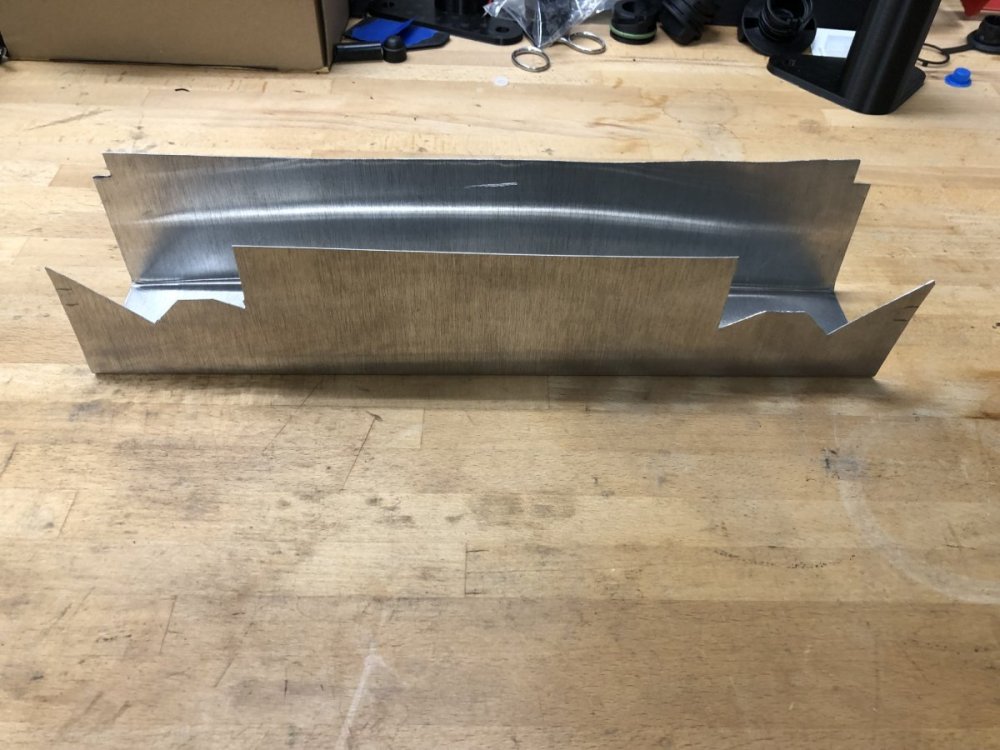
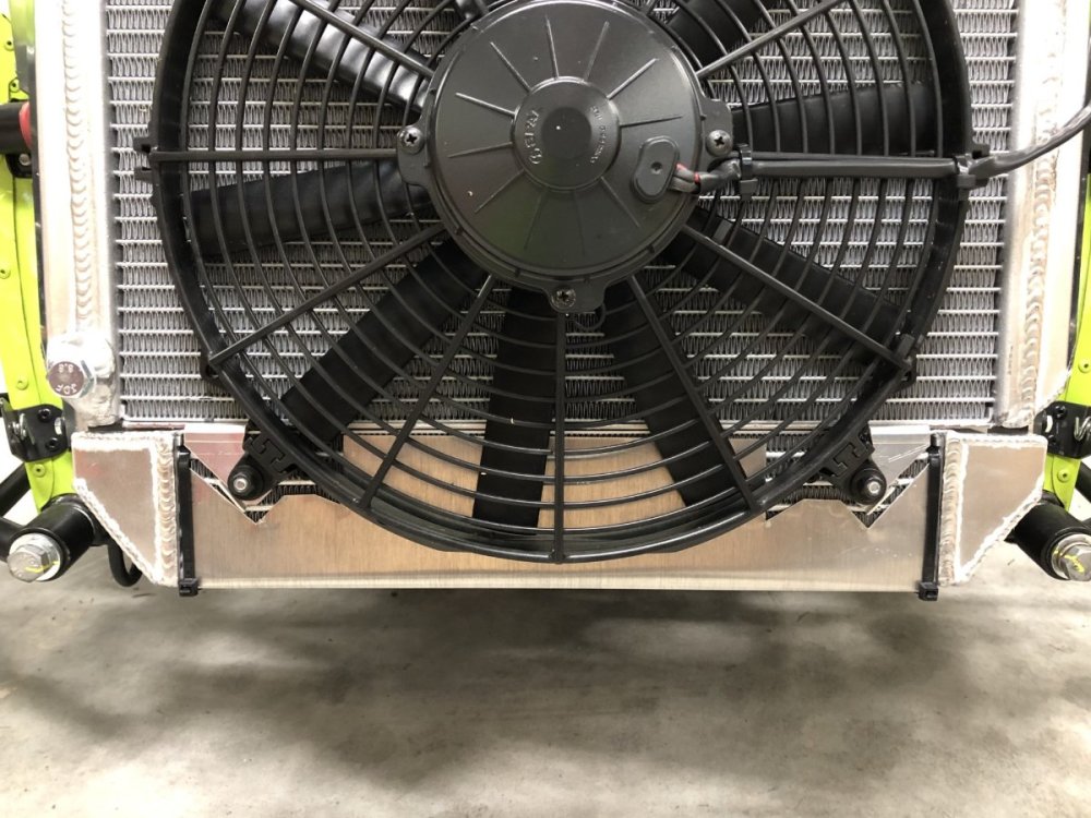
The crate engine, air box, ECU, dash, gauges, switches, dampers, factory fuel system, etc. Anyone want to build a car from my leftovers? I did a little fettling today then took the car out. Temps were still cool and the notorious oil over-cooling on these cars was present. As a result, I never took it over about 4500rpm but the engine felt good. I also seemed to really begin pulling strongly at part throttle at 4000rpm. To temporarily address the cold oil temps, I fabricated a simple block off plate out of thin aluminum. The clamping force is strong enough that it doesn't move once in place, and it is inset a bit, which results in the end caps preventing lateral movement. A couple of zip ties should ensure it doesn't vibrate off. I consider this V1, and suspect I'll make it to V3 or V4 before I'm satisfied. -John
-
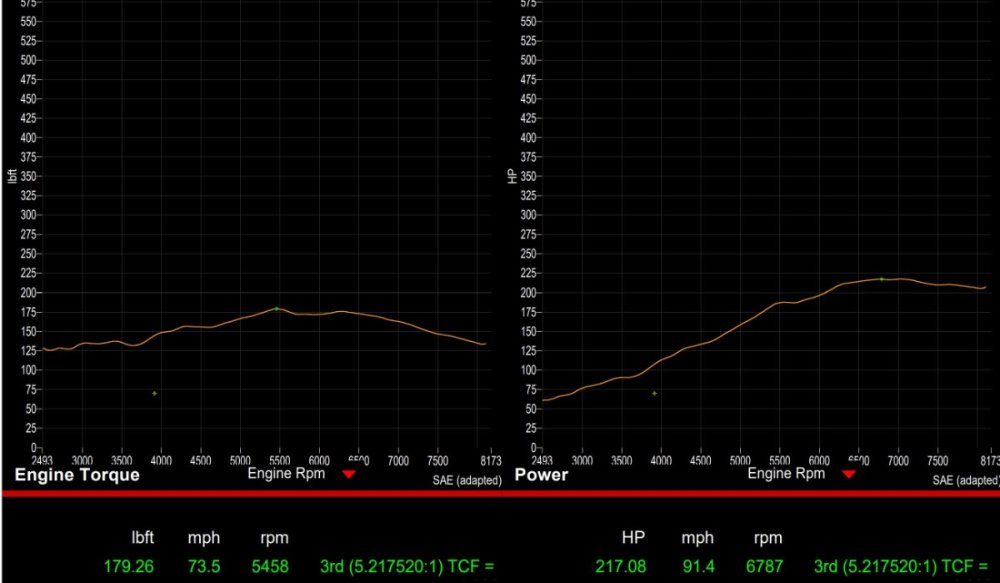
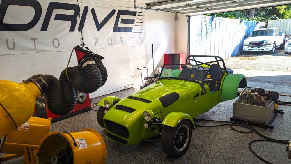
I picked up the car from the dyno this afternoon. It was a day later than expected, and as a result, my alignment appointment has been bumped to Monday. The dyno shop was very, very good. They went over the car in great detail, took pictures of everything they found (lots of little oil leaks that I missed), and kept great notes both on my expectations/instructions and their findings during the inspection. Attention to detail is very strong with them. If you are in the Seattle area, I highly recommend Drive Auto Sports in Everett. As mentioned previously, in theory this engine should be good for > 270hp at the crank, but with the stock 420 exhaust, which is undersized for this engine, the expectation was 250-260hp. If you assume a 15% loss, backing out the wheel hp reveals 255hp at the crank. Pretty much spot on to expectations. The ride home was uneventful but was far from traffic free. Consequently, I never had an opportunity to stretch the engine's legs and can't yet comment on how it feels or if the power level is good enough for now or if I'll want to pursue a larger exhaust over the winter and find another 15-20hp. I hope to get a better idea this weekend. -John
-
Someone suggested to use this Bosch sensor calibration. https://www.bosch-motorsport.com/content/downloads/Raceparts/Resources/pdf/Data Sheet_70101387_Temperature_Sensor_NTC_M12.pdf . I went with the RaceStudio suggestion of 2700 ohms for the pull-up resistor. I haven't yet confirmed the accuracy at operating temps, but measuring the oil in the dry sump tank with an infrared temperature sensor showed the dash reading was only off by about 4C with the temps in the low 60C range.
-
The advantage of this approach is that if you later opt for #1, you will already have the induction set up in place. The big decision is Roller Barrels or Throttle Bodies. TBs are a lot cheaper ($1500 - $2000 vs. >$5000) but they aren't necessarily a straight bolt-on and they don't have the same cachet of RBs at resale time. It might be worth a call to Raceline and speak to Peter (call the tech line) to get his thoughts and the latest on pricing. They use the Jenveys which work very well. If you do decide to go that route, ping me offline and I can walk you through some things at order time to save a few headaches. -John
-

The Regular Summary of Classified Ads of Se7ens Found For Sale
JohnCh replied to Croc's topic in Cars For Sale
No issues. Superformance was making their highly regarded Cobra replica for many years before introducing the S1. It is more civilized than most other se7ens, with luxuries like opening windows, and a real windshield. Depending on your perspective, that can be either a good thing or a bad thing. However, I've yet to hear an S1 owner say anything negative about their car. -
I had my appointment with SBD on Wednesday. Steve was helpful but unfortunately he was having connectivity issues on his side that impacted some of the session. However, I did get some questions answered and some changes made to the map. The ECU now controls my heated seats. I haven't yet confirmed they work, but according to the ECU it is switching the relay when the engine is running. Idle speed has also been adjusted from the as-delivered setting of 1200rpm to a calmer 1000rpm once operating temperature is reached. He also showed me some shortcuts, that sadly I have already forgotten. When looking at the really rapid TPS spikes I mentioned previously, he posited it's noise from the TPS. The speed site changes were following the changes in TPS voltage and were never spiking to full throttle which is what he would have expected if the sensor wiring was picking up the noise. It doesn't appear to impact drivability but is something I'll continue to watch. When I have time, I'll swap out the TPS for a spare and see if it's any better or worse. I put about 50 miles on the car Saturday with adaptive mapping enabled in an effort to further improve the map for the 30+ mile drive to the dyno this morning. That drive went well. It will stay at the dyno facility for a few days to dial things in. The hope is that it will be ready for pick up on Thursday morning, then it's off to Beachman Racing Friday morning for the alignment and to get the list of things I did wrong during the build. After dropping off the car at the dyno, I Ubered to a licensing office in that same city said to be familiar with the registration process. They were. In about 10 minutes I had plates! -John
-

Effective wind deflector/buffeting reduction?
JohnCh replied to Cueball1's topic in General Sevens Discussion
That's the key. It's also about the speeds you drive for any length of time as the buffeting ramps up the faster you go. You may find it's incredibly annoying at freeway speeds, but entirely acceptable at the sustained speeds you normally drive the car. -John -

Effective wind deflector/buffeting reduction?
JohnCh replied to Cueball1's topic in General Sevens Discussion
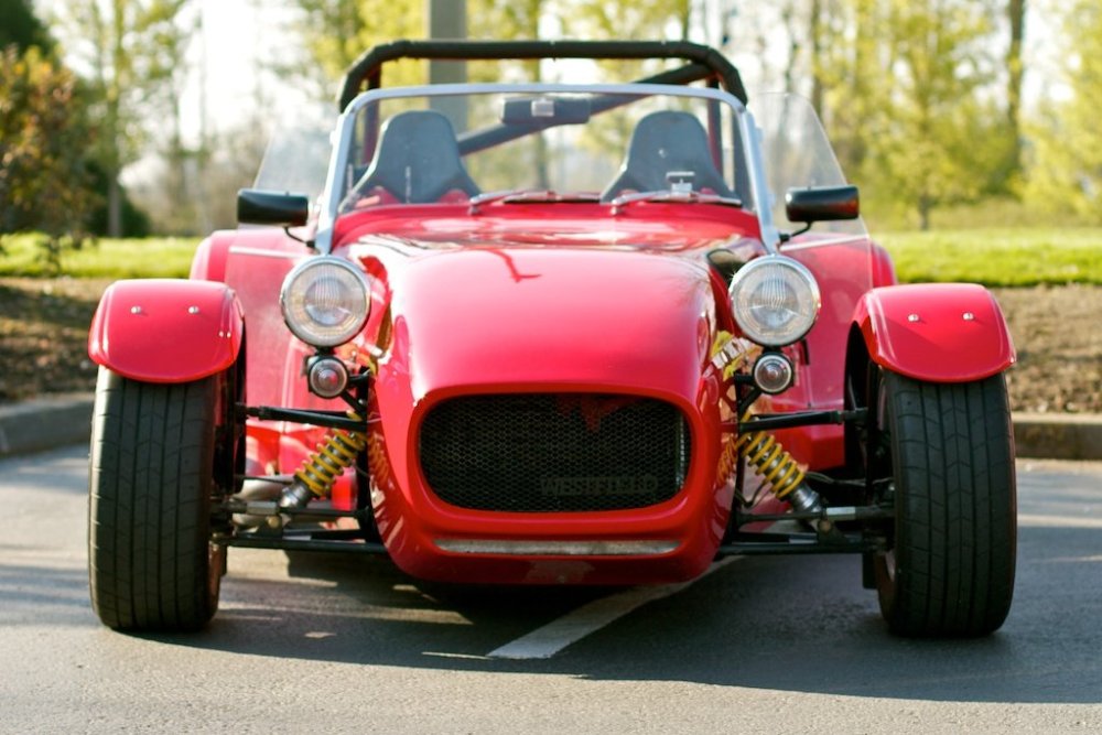
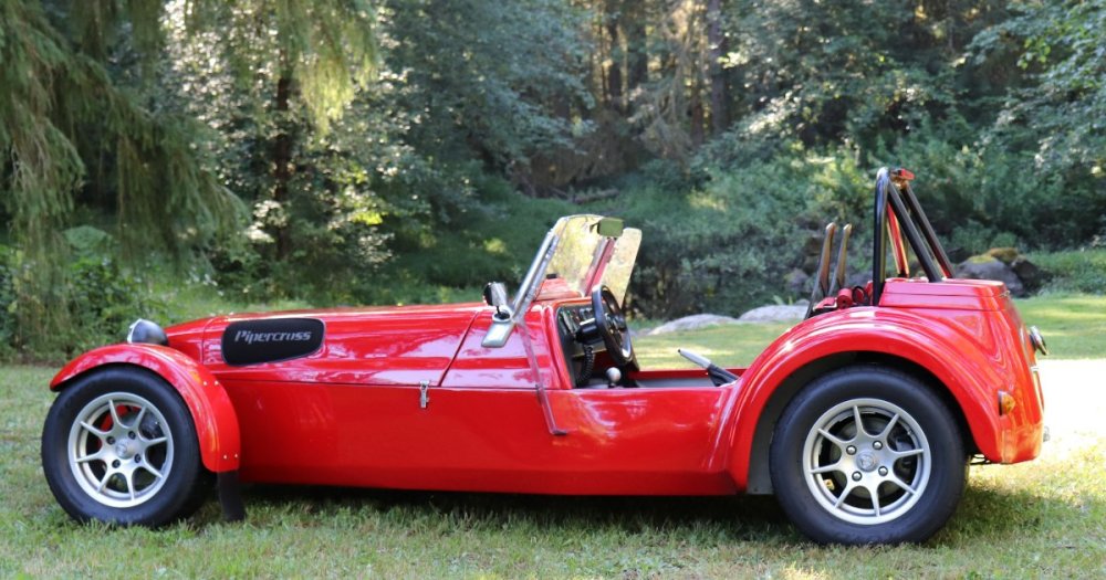
I experimented with this quite a bit on my Westfield prior to the USA2005 tour. The key was angle and length. These two photos show both: Ugly? Yes. Even worse aerodynamics? Yes. Effective? Absolutely. With the wind wings in place, turbulence is significantly reduced. Much closer to running with side curtains than to running without. A caveat is that each type of se7en is different. In my experience, the Westfield without wind wings is equivalent to a Caterham S3 with standard floors. However, a Caterham SV with lowered floors is a bit better. If you want to go down this route, my suggestion is to make mockups from wood (I used 1/8" hardboard and sections of 2x4) and find the angle and length that work best for your particular car. Once I had the final combo, I supplied that wood template to a shop that does Plexiglas work and had them cut and bend them from polycarbonate to match. -John -
I took a look in an exhaust port of my uninstalled 420 engine, and it appears to match SBD's photos of the high-port head with the bump out around the valve guide. -John
-

The Regular Summary of Classified Ads of Se7ens Found For Sale
JohnCh replied to Croc's topic in Cars For Sale
I think someone should consider switching to decaf -
I am far from an expert but have been researching the Duratec for the past 20 years and during that time have spoken at length with a number of tuners and owners on both sides of the pond who have built and dyno'd these engines. I've also had Duratecs in three different stages, each of which has been on the dyno. The following is probably more than you want to know but synthesizes what I've learned over that time. Hopefully others can fill in the gaps provided they can make it all the way through this post The 210-220hp range is an inflection point. Going beyond that puts you on the precipice of a steep, slippery slope thanks to piston-to-valve clearance limitations. Although you can "simply" pocket the stock pistons, that need leads many to do the as-long-as-I'm-in-there dance, resulting in new, higher compression, forged pistons that can already handle the higher lift, forged rods, keyed crank, fully balanced bottom end, headwork, etc. Been there, done that, and have no regrets. Depending on cams, you can comfortably get to the 235-260hp range without resorting to a forged crank and short rebuild cycles. The most verified power I've heard an engine make with 420 equivalent cams, Jenvey's, and headwork was 226hp. Most, however, come in the 210-220hp range. Heads are another consideration. I've been unable to determine which of the two Duratec heads are fitted to the 420. The early 2.3L from the Ranger and all US 2.0L use the same version, but when Ford added the 2.3L to the Focus in the US, they changed the head to something people later coined the high-port. The casting is different and accommodates larger intake ports; specifically, the area over the valve guide is increased. Ford of Europe used this head on the 2.0L in the Fiesta ST150 and possibly others, but I've never seen that casting on any US-based 2.0L. The stock head is good for about 220hp, removing a small exhaust tumble intended for emissions increases this to about 235hp, and the stock high port flows to 250hp. You can modify the low-port head to close most of that remaining gap. Some claim the high port head is an immediate 10+hp upgrade on any engine. Others state you need to have an engine already in that 220hp range to start seeing an improvement. I've never seen before/after data either way. There is also the 2.5L head which has enormous intake ports, and is bolt on, but does require some additional work to fit a se7en. I've also never heard stock power potential, but as the person who does my heads told me, the stock flow is less than one would expect based on the visuals. 250-260hp maybe? The reason the head matters is if the 420 uses the high-port head, you could probably knock on the door of 230hp with your current engine by adding roller barrels or throttle bodies, a good custom map and optimizing cam timing on the dyno. You'd probably be 5-10hp less if it's the low-port head. This is a lot easier, cheaper, and far less time intensive than rebuilding the engine as described above. It really comes down to the age-old question, how fast do you really need to go and how much do you really want to spend? -John
-
Another option is with the engine loom plug to which this harness connects. I've seen factory harnesses before where a pin isn't fully seated which creates an intermittent issue. Easy enough to check and rule out.
-
Caterham has just delivered a bespoke optioned 420R for Evo magazine. Things I haven't seen before are the Alcantara covered dash and center tunnel, and houndstooth upholstered seats. The combination of roll cage, S seats, and the 10-way Bilsteins and central fuel filler from the 420Cup, is certainly unique. It should be interesting to watch what they do with it. https://www.evo.co.uk/caterham/7/206061/caterham-seven-evo-edition-revealed-bespoke-420r-joins-the-fast-fleet -John
-
In my experience, when it comes to boundaries, many people don't view se7ens in the same way as a normal car. I have caught a 4-year-old trying to climb into my car at dog park while using the silencer as a stepping stool. Parents watching their 10-year son attempting to get behind the wheel while the family stood around the car in a store parking lot. And foreign tourists at Mt. Rainier asking in broken English if they could take photos of my car, only to find them a few minutes later taking those photos while one of them posed behind the wheel. I suspect the desire of some miscreants to take a souvenir of the encounter is also higher than normal which is why I didn't option either the quick release wheel or the master cutoff switch. To be fair a lot of people have those and have never had an issue. But with my luck, I wouldn't be in that category. -John
-
I pinged Caterham about a 22% rack for the SV since I didn't see one listed on their web store. I'm sure their answer isn't new information for a lot of people, but it was to me: "we only offer a 22% for non SV cars as the steering rack body is different on an SV." -John
-
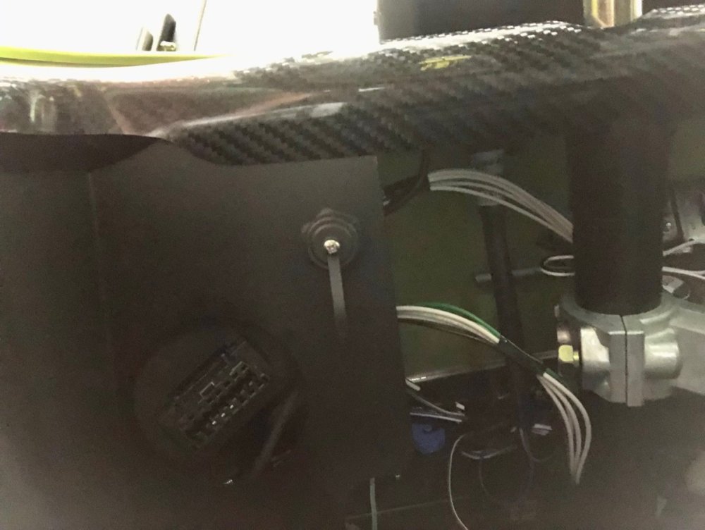
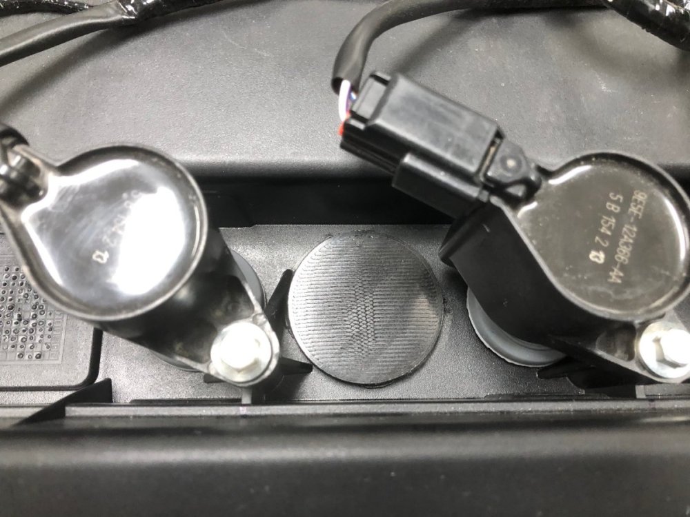
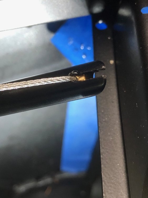
In preparation for the dyno, I took care of some things I previously punted for various reasons. The big one was soldering in the pull-up resistor for the oil temperature sensor so the AiM could read it correctly. That necessitated removing the scuttle, which is very easy to do after the conversion from rivets to rivnuts with M4 fasteners -- highly recommended mod. The AiM now reads about 9 degrees cool at room temperature. Once I run the car again, I'll check accuracy at running temps and adjust the calibration accordingly. I had also planned to install the remote button interface for the AiM which provides a dedicated button to reset the trip odometer. However, when attempting to install it, I discovered my mount for the AiM makes that a difficult process. When doing the original design, I had incorrectly assumed this was a push in fitting. It turns out it's screw in. With insufficient finger space, I was faced with removing the rear mount, or punting again and doing this as a winter project which includes printing a slightly redesigned rear mount. I've gone with option two. That means rather than resetting the trip odometer with a single push of the button on the steering wheel, I need to go through a couple of menus on the display. Not a huge inconvenience. I also ran power to the 12V outlet attached to the glove box and confirmed the on/off switch is doing its job to stop parasitic drain from the USB adapter. The knee trim panels finally went in, with the driver's side first drilled to mount the data port for the AiM. The Element fire extinguisher was installed above the passenger footwell. Easy to reach, but not in a location that screams "steal me!" Next was adjusting the throttle pedal stop and putting silicone on the throttle cable ferule where it mounts in the top of the accelerator pedal. A close look revealed that at full throttle, the rough, sharp edge of the cable cutout pushes into the cable. That seems like an eventual break point. A few minutes with a small file rounded over the edge. I also attached the cover I printed to plug the hole for the cylinder head temperature sensor Ford uses in most applications of the Duratec. Without this plug, water can fill the void that leads to the top of the spark plug ports for #2 and #3. The 420 uses a valve cover that doesn't have this opening. I've never seen it on a US car so perhaps it's a European fitment. Does anyone know the source, or if Caterham has these modified? Finally, I did some general clean up: removed last vestiges of blue tape, cut off the ends of any zip ties I missed earlier and sealed a couple of unneeded holes in the firewall with rubber grommets. Next step is the dyno on the 14th-16th, followed by an alignment, and (hopefully) registration. If things go well, my 420R garage sale is just around the corner. -John
-
Dez, a quick check of the Burton catalog shows two manifolds. The Details section of each page has dimensions, including the angle. If you haven't already seen this, it might be worth comparing these to your modified manifold and pay particular attention to how your carbs are currently located. How much clearance before any part of them contact the bonnet and also clearance over the top chassis rail. https://www.burtonpower.com/inlet-manifold-ford-1-6-x-flow-ohv-kent-2x40dcoe-3-1-im4242a.html https://www.burtonpower.com/inlet-manifold-ford-1-3-x-flow-ohv-kent-2x40dcoe-4-25in-im4240a.html They also sell a kit with the Webers. It's hard to tell, but it almost looks like the intake manifold length may be slightly different than the other two. Might be worth contacting them to ask. https://www.burtonpower.com/weber-twin-carb-kit-40dcoe-x-2-ford-x-flow-ohv-webpfo202.html -John
-
There is a member here with the same username as the person who won the BaT auction. Might be worth sending a PM to see if it's him.
-
Thanks Bob. Once I have a chance to drive the car hard, I can determine if the seats are too loose and require additional padding. My guess is they are just fine. A little looser than I prefer and not as optimal for me as the Mogs, but more than good enough. The dyno is scheduled the week of the 14th, with the alignment hopefully happening around that same time. Once those two things occur, I should be in a position to better evaluate all aspects of the car.
-
Steve Nichols, who designed the hugely successful McLaren MP4/4, has released a new car. Given the pedigree, this should be a very special driving experience. Time to start a GoFundMe page. https://www.autoblog.com/2023/07/27/nichols-cars-n1a-can-am-mclaren/ -John
-
Thanks, was this something that happened with increasing frequency or was it just random and occasional? I think I'll pull the scuttle this weekend to finish up a few jobs in preparation for the dyno and registration and see if jiggling that ground connection to the AiM does anything. The ground for that circuit has two connections I introduced: the connection to the Binder plug for the AiM harness and the connection from the factory gauge harness to the 24 gauge wire required by the Binder plug. I'll also check the sensor connector and pin into the ECU connector.
-
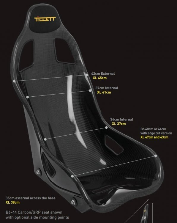
For the heck of it, I measured the width differences between the Tillets and Mogs. It's about 10mm at the hips and 20mm further forward about the location of the crotch strap cutout. Bigger than my estimation above which explains why I notice it, but again, not a massive difference. I also tried the car again, repeating the ring seating process to see if I could replicate the weird oil pressure readings from yesterday. Nothing. Oil pressure read perfectly normally during the entire drive. Intermittent electrical issues are such a pain. I'm hoping this was some really weird anomaly that doesn't reappear so I can proceed with the dyno session.
-
It wasn't a complaint. it was an observation.
-

The Regular Summary of Classified Ads of Se7ens Found For Sale
JohnCh replied to Croc's topic in Cars For Sale
When your Ariel Atom just doesn't draw enough attention.... I'm curious if the build is documented anywhere? It may not be to my taste, but it's fascinating as a build project. I wonder how far gone the original Europa donor was before this began? -
Yes, they are definitely the S3 version; labeled and measured. The difference in width to the Mogs is slight, but noticeable to me. I wouldn't characterize the seats as loose, but they are not quite as snug as the Mogs which are similar to the older R500 seats in this regard. I'm not sure anyone else would notice the difference, but there is a subtle reminder for me each time I get in the car. With the Mogs, the fastest entry is done with one hip pointing slightly downward, then rotating my hips once it passes the lap belt. Sitting with both hips level results in the belts being caught between my hips and seat and often wedging in place. With the Caterham's seats, I can sit straight down without this happening. Yes, the belts touch my hips, but it's not tight enough to pull them down. I haven't measured but I suspect there is a very slight difference between the two in this area. Maybe 3-5mm? By contrast the SV seats have noticeable gaps between my hips and the sides. The photo below shows the differences between the two versions of the carbon fiber seats. Tillet didn't provide a measured drawing of the R500 seats, but he did provide the following about the differences: "The original Caterham R500 seat was not made for a crash helmet or Hans device so when we made the 620R seat we moved the headrest back ¾ of an inch and lifted the belt holes. The inner shape of the 620R/ B6 is very slightly larger and the lack of side carpet also give a little more room. The B6 620R version is more symmetrical in the seating area and has a carbon top layer facing forward only. The R500 seat has an epoxy carbon Kevlar front and rear surface, with a black vinyl glass base moulding. The base frame of the 620 R seat is handed and tipped in towards the centre to give a better driving position with the shoulders inside the car. Nothing that cannot be done to the R500 seat with two 8 mm spacers under the outside runners." -John


