-
Posts
3,266 -
Joined
-
Last visited
Content Type
Profiles
Forums
Store
Articles
Gallery
Events
Library
Everything posted by JohnCh
-

Could the older Stalkers be a wise purchase ?
JohnCh replied to preventec47's topic in General Sevens Discussion
Given the small community of US & Canadian se7en owners, and their wide range of knowledge that spans makes, it is a conscious decision to avoid model-specific forums. If we did take that approach, we would have them for Caterham, Birkin, Superformance, WCM, Westfield, Brunton Stalker, Locost, and others. Although that may make researching a specific make easier, it reduces eyeballs on an issue as many people gravitate towards what they own, and some may intentionally avoid a specific brand forum. e.g. A Westfield owner with expertise on the crossflow, may miss a question posted to the Caterham forum about a crossflow problem because, well...it's a Caterham. Our belief is that the community is best served if we pull together and try to help each other out rather than build unintentional brand barriers. Hopefully someone -- who may or may not own a Stalker -- will answer your question. -John -
Thanks, but I'm thinking about a different direction. With the internal fittings, there is only room to raise the pump about 1/2" and still accommodate the bend in the output hose which is required for fitment -- space is really tight. Current thinking is to replace the Hydramat with a slightly larger version that positions the collector at the end rather than in the middle and attempt to position the pump end so there is a short, nearly straight shot to the Hydramat, thus eliminating both 90 deg fittings. I need the pump back to play with this and ensure I can make it work. The hoses are rated for in-tank placement. One thing Deatshwerks brought up is wiring. The pump (255 LPH) runs at a little less than 10 amps. I believe, but need to verify, the fuel pump wire is 16 gauge, which technically is fine for that amperage. Deatschwerks, however, likes to use 12 gauge wire. Running new wire is doable, but a pain. Any thoughts there? Is anyone running a larger pump with stock Caterham wiring? Thanks, John
-
I heard back from Deatschwerks. The pump passed the warranty test, but during the endurance test there was "a slight hiccup in amperage most likely from brush break in." They feel it's within spec but opted to replace it in good faith. I also purchased injectors from them and made a few pre-sales technically enquiries during that process. Every experience with them has been very, very positive. Even opening the support ticket online resulted in a response within 30 minutes. Deatschwerks is based in OK and worth keeping in mind for fuel system products: https://deatschwerks.com/ I'll test the new pump before making other changes. However, once the issue reappears or I am confident that was the source, I'll update the in-tank plumbing to minimize resistance. -John
-
When you aren't following a well-traveled path, issues are expected, and in a twisted way, part of the fun. Quite frankly, I'm really surprised this is the first real problem I've encountered, but if indeed it is a confluence of design elements in the fuel assembly, it should be a relatively straightforward fix. I've already redesigned the assembly lid to retain both the fuel pump bracket and return hose fitting while adding a massive inspection port which should take the guess work out of the equation. I'll print that later today. And if you think this is challenging, imagine how hard it must be to ensure all the correct parts are included in an expensive kit. Caterham has been doing this for 50 years, yet they still can't figure out how to do it -- it must be monumentally hard <sarcasm mode off>
-
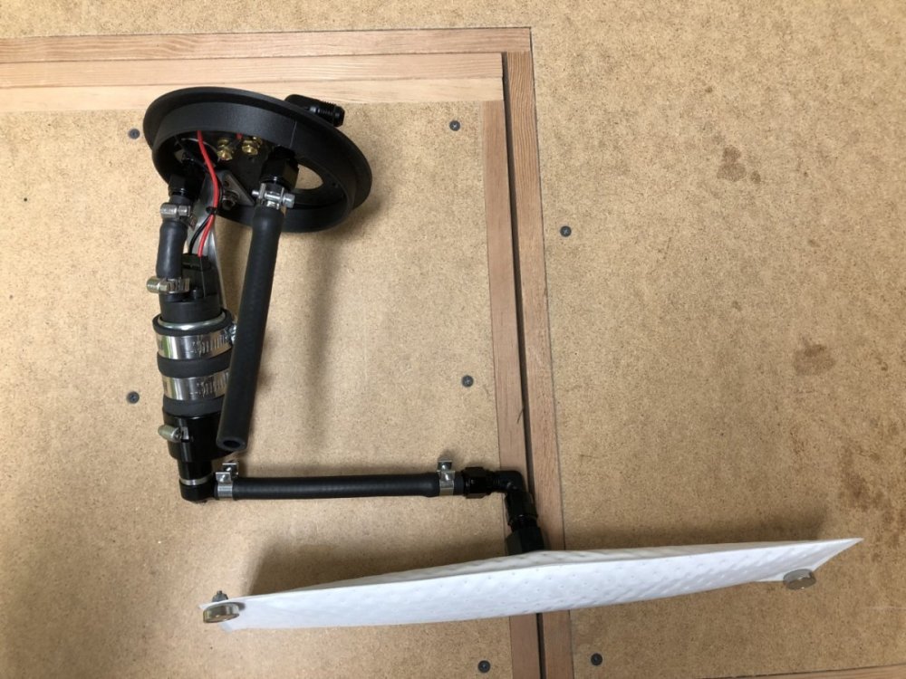
I just had an interesting conversation with Holley. There are a few potential issues with the installation that could create either too high a load for the pump ( @Rosteri's theory) or over aeration of the fuel from the return line ( @sf4018's line of thought). Looking at the photos of the assembly out of the car, and remembering the fuel level when I removed it, made me realize that the return may have been hitting the floor and aerating the fuel. If excessive, this could cause issues for the Hydramat. More likely though is the two 90 degree fittings and 12" of hose between the Hydramat and pump creating too big a load for the pump to overcome. Another possibility is that hose rides up the slop of the tank floor, creating a high spot in the routing that traps an air bubble. While I wait for the pump to be returned, I'll print a new fuel assembly lid with inspection ports to let me see how everything sits in the tank, then figure out a game plan. It most likely involves a new Hydramat with an offset collector that can be placed closer to the pump, and possibly changing the angle of the pump mount to allow a straighter shot to the Hydramat fitting. Thanks for the insights and stay tuned. -John
-
Thanks @Anaximander, the stalling began after driving 2 miles in a neighborhood with air temps around 58F. I'm not sure if that combination is sufficient to create pump or fuel overheating issues, but I'll ask Holley for more info on this when I speak with them.
-
It's designed to work with either return or returnless and with much higher flowing pumps than I'm running. For return style, they want the hose pointed about 1" above the collection point. I believe that's how I installed it, but given it's somewhat blind, it could be off by a bit. I'll ask them about that as well. Thanks, John
-
I did confirm there was fuel in the tank when I removed the fuel pump -John
-
Oops. Fair point. I'll call Holley and ask if there are any undocumented recommendations regarding fuel pump compatibility. I suppose another remote possibility is the hose between the Hydramat and pump is collapsing. I'll examine that closely when I reinstall the pump. I still wonder about the weird TPS spikes as the engine stalled.
-
Thanks @Anaximander but I have already fabricated the module as shown below and have the Hydramat, so the only difference is the pump, which seems to be one of their standard in-tank pumps. Thanks, John
-
Thanks @Rosteri , I'll keep that in mind and add it to the troubleshooting list. However, this pump is designed to work in tank and pulling from a filter, although much smaller and a different design than the Hydramat. Also, it happened a few times at idle, when demand on the pump was very, very low. A big concern is Deatschwerks giving the pump the all clear, then after reinstalling it, the issue goes away or is very, very sporadic making it even harder to troubleshoot.
-
The full plan if the pump checks out is to Get SBD to confirm the TPS spikes are not indicative of an issue. If they are not, then: Try getting it to repeat the issue while driving on my property with bonnet removed and action camera affixed to windscreen, pointing downward at the fuel pressure gauge and streaming live to my phone. Using extensions currently on order, place multimeter in front of me and attach the alligator clips to the fuel pump terminals. If still inconclusive: Plumb in a fuel pressure sensor to log everything and confirm that fuel pressure issues do not occur prior to Lambda going lean.
-
@sf4018 that's what I plan to try if Deatschwerks states the pump is ok. My initial assumption was that's the issue, but then testing with the multimeter showed 12v at the pump terminals (post relay) while the engine was dying, rather than immediately prior. If the pump checks out okay, then I'll assume user error with that reading (twice!) and bypass the relay to see what happens.
-
Thanks @Anaximander , those little things are always the hardest to track down. I'm using the Caterham ECU with a revised map from SBD who distribute that ECU. The installation is factory until the fuel pump, and the only electrical change in that ecosystem is swapping the PWM module with a relay still controlled by the ECU. The initial running issues feel like they are down to the map which will be sorted on the dyno. My objective was simply getting it running well enough that it can be safely driven there. The issue that has me on hold appears to be the fuel pump. If that's not it, I'll confirm with SBD if the odd TPS spikes when the engine is stalling are normal or indicate an issue elsewhere, including with the ECU. If that is also a "no", there are a few other things to test once the fuel pump is back provided the issue remains somewhat repeatable. Intermittent issues are always a challenge. -John
-
Curious to know how long it will take them to sort that "minor" mistake.
-
Inputs, but not that implementation. The MAP sensor used by Caterham is actually a combination sensor that is used for barometric and air temperature. Load Site is only controlled by TPS.
-
Thanks @MV8, a few additional details based on your advice. This is a TPS-only system using a Colvern unit which is the common TPS on Jenvey installations. That spiking is only occurring after the Lambda has started going lean. It's normal everywhere else, so at this stage I don't think it's a TPS issue, but I have spares in case that becomes a problem. Lambda is provided by a single WBO2 with an AEM X-Series EUGO controller feeding the MBE which SBD programmed to read based on AEM provided calibration data. At this point, things are run open loop -- i.e. it is purely in read mode so has no impact on running conditions. I also went through all the other logged data and everything appears normal. No unexplained corrections, temperature spikes or dips, no error codes, etc. Thanks, John
-
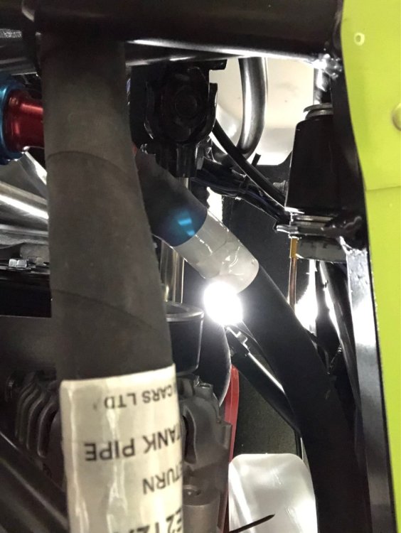
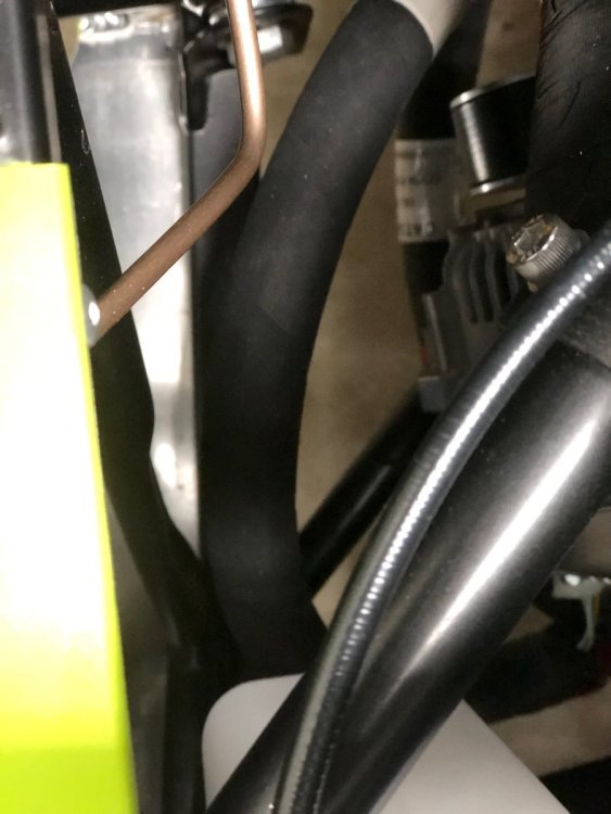
Here are two hastily taken photos to supplement those provided by Wallisek. For reference, the first photo was taken with the phone on the ground looking up at the bottom of the chassis. The top of the photo corresponds to the front of the car. The second photo shows that same hose from above. Although it doesn't look like it in the photos, there is clearance to the chassis tube. Don't let the white plastic bottle at the bottom of each photo confuse you. I mounted my windscreen washer bottle there to get it out of the way. -John
-
Just heard back from SBD regarding scheduling time to go over my questions. I was wrong about the hourly rate I mentioned earlier. It's 160 GBP for "up to an hour." That's over $200 at the current exchange rate. As @sf4018 wrote earlier, very expensive. -John
-
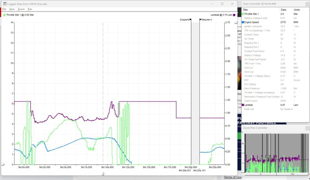
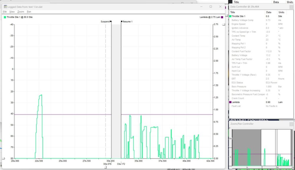
I looked at ore of the logs and that really rapid TPS spike frequently occurs after the engine has gone full lean and is stalling. An example is below. I then tried to rapidly blip the throttle to see if I could replicate that instant increase and decrease. As you can see, they are not that instantaneous. BTW the grid lines in both screenshots represent 1.25 second intervals, but I can't get the SBD graphing software to make the grid lines the same width. The scaling appears to be tied to the length of the logging session and this one is too short, slightly increasing grid line width compared to the previous screenshots. The nature of these spikes makes me wonder if it's an artifact from how the ECU reacts as it's shutting off from rapidly reduced crank speed. Any thoughts? The fuel pump went back to Deatschwerks yesterday. I hope to hear back from them in about a week. -John
-
Routing it between the chassis tube and side skin is specific to the S3. It is a fiddly fit on the SV - I remember a lot of swearing when I did mine -- but it will fit without rubbing. If no one has a picture, I'll see if I can take one later. -John
-
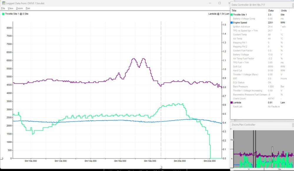
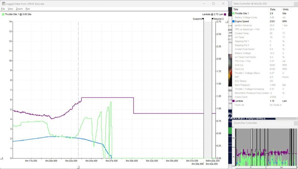
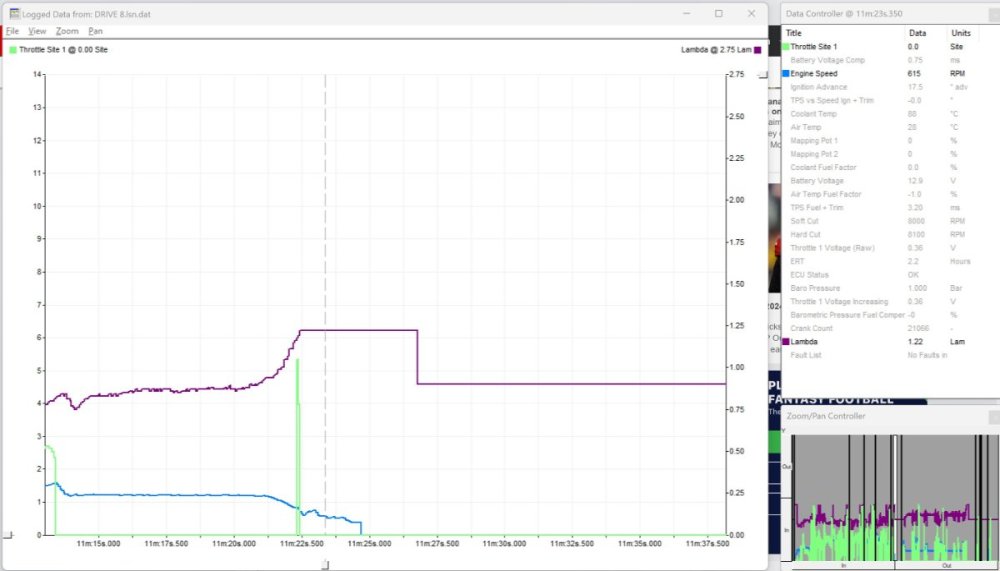
Thanks, @MV8, this is essentially what I did earlier. I didn't have jumper leads long enough to place the DVM in my lap, but it did reach the back of the tunnel. As the issue would start, I could swivel my head to see the reading. The initial diagnosis made while watching the fuel pressure gauge was what led me to do the DVM setup. The logs show a very minor rpm dip (100 rpm?) when the spikes were brief. Here is an example I screen captured when going over the logs from an early drive on Saturday while chasing the initial mixture issues. The spike doesn't go fully lean, reaching about 1.12 and lasted nearly a second. This next one shows when it led to a stall while driving. As you can see, it started to lean up which led me to add a small amount of throttle then some quick blips to see if anything would change as the revs went to zero. And lastly leading to a stall while idling. I'm not sure if I intentionally blipped the throttle, or that was a result of me moving in the seat to look at the DVM or the fuel pressure gauge. That said it is very brief - 1/10 of a second? -- and with no ramp or fall off. Can that happen with a mechanical throttle setup? I'll look for more examples like that when I have time later. -John
-
I didn't add a fuel pressure sensor (hindsight...). However, when testing in the driveway I pulled the bonnet and could see the fuel pressure regulator gauge from the driver's seat when leaning forward. It fell off a cliff when the lean spikes hit that led to a stall. To be fair, there was a slight lag as I looked to the gauge, so I won't claim 100% certainty, but it's close. The pump is out of the tank and the fuel is evaporating. I'll pack it up tomorrow and send it back for evaluation. -John
-
Here is what SBD told me: "Because you are going to be using a normal fuel pump and regulator, I have programmed the same pin to be simple on/off output to control a relay that you will have to fit which will replace the standard Ford electronic fuel pump control module. Please note that this will be a switched ground as all output are on the 9A4 ECU. " I used this waterproof relay and located it in the same location as the control module next to the tank. I have the wiring information with color codes in my notes. Happy to dig those out if you need them. As for SBD being pricey. Don't get me started. Unlocked ECU was 583 GBP, the special sauce cable to connect it to a laptop is 160 GBP, and the map was an additional 320 GBP. Any support is extra. I don't recall the exact price but it was in the 125 GBP per hour ball park. By comparison, the Emerald is 695 GBP for an ECU with a lot more features (4 wheel traction control, switchable maps on the fly, knock control, etc.), the laptop connection cable is 20GBP, and they give you starter maps gratis. They also don't charge for support and when I have offered in advance to pay for some extra help if needed, I was always told not to worry about it. Unfortunately, getting SBD to do a live session on roads is difficult for me. As @Croccan attest, cell service is really poor in my area. I may still use SBD to help with the dyno session. -John
-
Thanks, but I'm not using that controller. Since I have a return system controlled by a pressure regulator, SBD had me replace it with a normal relay that the MBE still controls for on/off only. The thinking is that if you are in a crash that kills the engine, the MBE will cut power to the pump and stop it from emptying the tank. The fact that the terminals on top of the tank, which feed the pump, were still showing 12v when the engine was going full lean and stalling, and not going to 0v until after the engine stops, makes me think it's the pump or an in-tank connection.


